Charged particles accelerator apparatus, charged particle gun and method of accelerating charged particles

Active Publication Date: 2017-09-14
DEUTES ELEKTRONEN SYNCHROTRON DESY
View PDF3 Cites 3 Cited by
  • Summary
  • Abstract
  • Description
  • Claims
  • Application Information

AI Technical Summary

Benefits of technology

[0023]Operating the accelerator apparatus with single cycle pulses results in the following further advantage. Empirical studies had initially shown that electron field emission, scaling as f1/2/τ1/4 with f the operation frequency, and τ the pulse duration of the accelerating field, imposes a principal limit on device performance. The above approximate scaling behavior justified developments of accelerators towards higher operating frequencies and ultrafast schemes to achieve compact accelerators. However, recent studies on breakdown thresholds of various accelerators demonstrated that pulsed heating of the accelerator walls is the dominant factor limiting acceleration gradients. This conclusion confirmed the observed lower operational gradients in existing facilities when compared with predictions from the previously derived scaling laws. It was concluded that the pulse duration of the accelerating field plays the major role in the breakdown event, since it is directly linked to the pulse energy governing the pulsed heating in the device. Therefore, adapting the efficient acceleration to the use of short pulses opens new potentials to shrink down the size of accelerators.
[0024]According to a second general aspect of the invention, the above objective is solved by a charged particle gun, comprising a single cycle pulse source device being configured for delivering a sequence of linearly polarized single cycle pulses with a linearly polarized plane wave shape, an accelerator apparatus according to the above first general aspect of the invention, being arranged for receiving the sequence of single cycle pulses, and a particle source device being configured for providing charged particles (particle bunch, particle pulse) to be accelerated at the injection section of the accelerator apparatus.
[0025]Advantageously, the invention provides a compact charged particle gun, in particular electron gun which operates based on single cycle pulses. Due to the ultrashort pulse duration, the limitations caused by electrical damage of the accelerator walls are strongly relaxed. Therefore, the single-cycle pulses can potentially be focus

Problems solved by technology

Although these systems represent highly developed techniques with strong acceleration capabilities, they have substantial shortcomings in terms of efficiency, size and complexity of operation, resulting in limited applications, e.g., in research on basic and applied sciences.
However, the acceleration schemes based on optical pulses suffer from difficulties caused by the short optical wavelengths.
However, these techniques have limitations as the waveguide used is

Method used


Image

  • Charged particles accelerator apparatus, charged particle gun and method of accelerating charged particles
  • Charged particles accelerator apparatus, charged particle gun and method of accelerating charged particles
  • Charged particles accelerator apparatus, charged particle gun and method of accelerating charged particles

Examples


Example

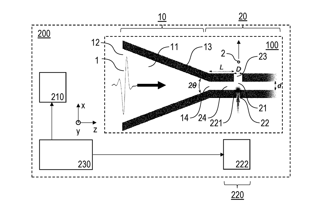
[0051]FIG. 1 schematically illustrates a first embodiment of an accelerator apparatus 100 with a horn-shaped coupling device 10 having one horn coupler 11 and a waveguide device 20 having an injection section 21. A charged particle gun 200 includes the accelerator apparatus 100, a single cycle THz pulse source device 210, a particle source device 220 and a synchronization device 230 synchronizing the single cycle THz pulse source device 210 and the particle source device 220. Typically, at least the accelerator apparatus 100 is evacuated, i.e., a vacuum is provided in the coupling and waveguide devices 10, 20. Alternatively, the accelerator apparatus 100 can be operated e.g., with atmospheric pressure, in particular at ambient air.

[0052]With reference to the Cartesian coordinates, the accelerator apparatus 100 is arranged for an input of single cycle THz pulses 1 travelling with linear polarization along a longitudinal beam direction (z-direction). Accordingly, the electric field of...

Example

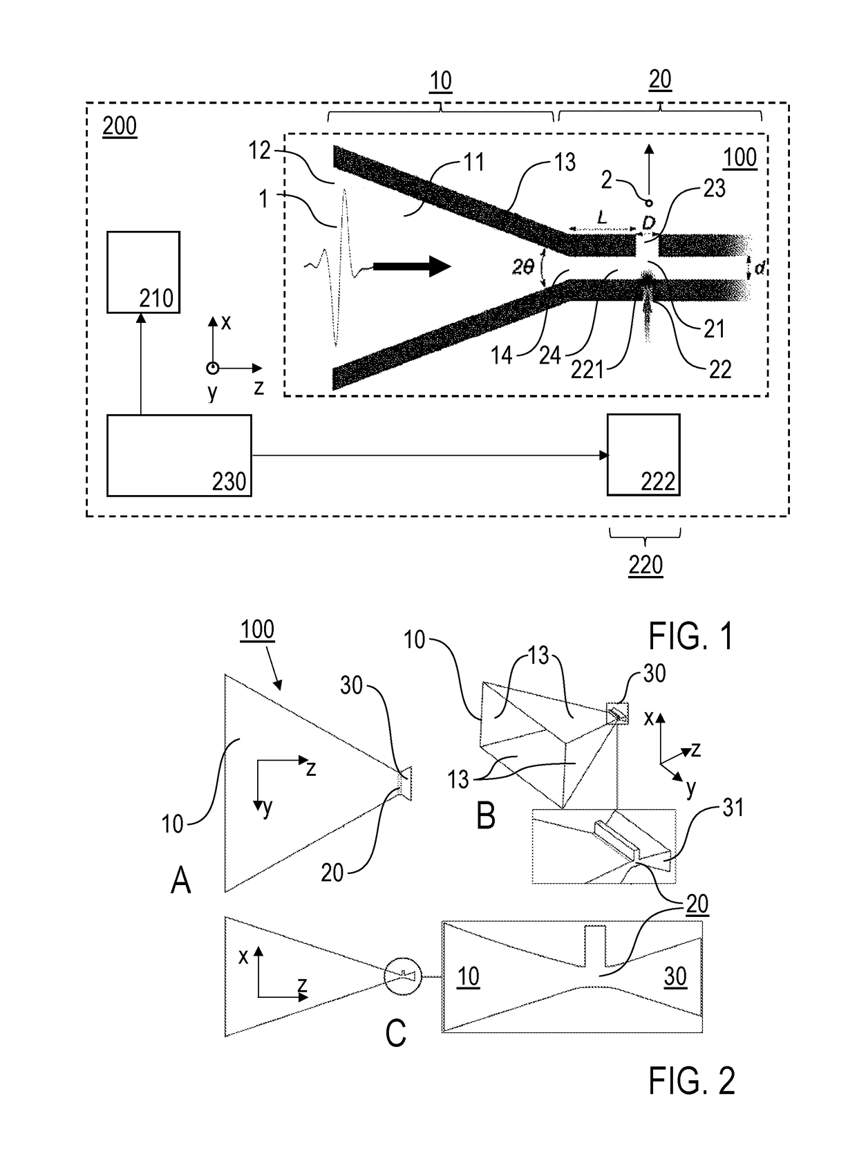
[0062]In FIG. 2, the accelerator apparatus 100 of the second embodiment of the invention is illustrated with a top view, e.g., along y-direction (FIG. 2A), perspective views (FIG. 2B) and side views, e.g., along x-direction (FIG. 2C). On one side of the waveguide device 20, a single horn coupler 10 is provided, while a reflector device 30 is arranged in opposite side of the horn input coupler 11. The reflector device 30 comprises a horn antenna 31, which is arranged with λ / 4 distance from the injection section 21.

[0063]The horn angle of the horn antenna 31 is equal to the horn angle of the horn coupler 11, while the longitudinal length of the horn antenna 31 is selected such that the single cycle THz pulse 1 arriving at the injection section 21 is superimposed with the reflected single cycle THz pulse. This superposition leads for a half-cycle time a constructive interference between the leading edge of the pulse and the decelerating half-cycle, which due to reflection is now accele...

Example

[0069]The configuration of the third embodiment of the invention is illustrated in FIGS. 4 and 5. In FIG. 4A, a perspective view of a wavefront shaping structure 40 of the accelerator apparatus 100 according to the third embodiment of the invention is schematically illustrated, FIG. 4B shows top views of the accelerator apparatus 100 in the y-z-plane, and FIG. 4C shows a two-dimensional presentation of the wavefront shaping structure. FIG. 5 shows a charged particle gun 200 including the accelerator apparatus 100 of FIG. 4. It is noted that the third embodiment as illustrated in FIG. 4 can be modified with the features of the embodiment of FIG. 2. Accordingly, the accelerator apparatus 100 provided with the reflector device may include the wavefront shaping structure as described in the following.

[0070]The accelerator apparatus 100 comprises the horn-shaped coupling device 10 with two horn couplers 11, 15 being coupled with the waveguide device 20. The horn couplers 11, 15 are arran...


PUM


Abstract

Accelerator apparatus (100) for accelerating charged particles (2) with pulsed radiation includes horn-shaped coupling device (10) with at least one horn coupler (11, 15) having input aperture (12), electrically conductive walls (13) and output aperture (14), wherein pulsed radiation is received at input aperture and focused towards output aperture, and waveguide device (20) coupled with the output aperture and configured for receiving focused pulsed radiation. Waveguide device includes injection section (21) for providing charged particles and subjecting them to acceleration by pulsed radiation in injection section, and lateral output port (23) for releasing accelerated charged particles along particle acceleration direction. The at least one horn coupler receives linearly polarized single cycle pulses (1) including broadband frequency spectrum shaped as a linearly polarized plane wave and focuses linearly polarized single cycle pulses. Waveguide device has non-resonant broadband transmission characteristic. Furthermore, charged particle gun and method of accelerating charged particles are described.

Description

CROSS-REFERENCE TO RELATED APPLICATIONS[0001]This application claims priority from EP 16 000 590.6 filed Mar. 11, 2016, which is incorporated herein by reference in its entirety.BACKGROUND OF THE INVENTION[0002]The present invention relates to an accelerator apparatus, being configured for accelerating charged particles with pulsed radiation, preferably in a THz or RF wavelength range, in particular including a horn-shaped coupling device and a waveguide device with a particle injection section. Furthermore, the present invention relates to a charged particle gun including the accelerator apparatus, and to a method of accelerating charged particles, like e.g., electrons or protons. Applications of the invention are available in the field of compact particle accelerators, e.g., included in X-ray sources, or for electron diffraction imaging.[0003]For describing the background of the invention, particular reference is made to the following publications:[0004][1] E. A. Nanni et al. in “...

Claims


Application Information

Patent Timeline
IPC IPC(8): H01J29/48H05H15/00
CPCH05H15/00H01J29/481H01J37/06H01J37/08H01P3/12H05H5/00H05H5/047
Inventor FALLAHI, ARYAKAERTNER, FRANZ XAVER
Owner DEUTES ELEKTRONEN SYNCHROTRON DESY
Why Eureka
Try Eureka