Drive unit for an elevator

Inactive Publication Date: 2008-09-09
INVENTIO AG
View PDF21 Cites 4 Cited by
  • Summary
  • Abstract
  • Description
  • Claims
  • Application Information

AI Technical Summary

Benefits of technology

[0005]The advantages achieved by the present invention are essentially that a drive unit with a short shaft and therefore a short overall length of the drive unit can be realized. It is also advantageous that

Problems solved by technology

A disadvantage of this known device is that the forces acting on the rigid axle are unfavorably distrib

Method used


Image

  • Drive unit for an elevator
  • Drive unit for an elevator
  • Drive unit for an elevator

Examples


Example

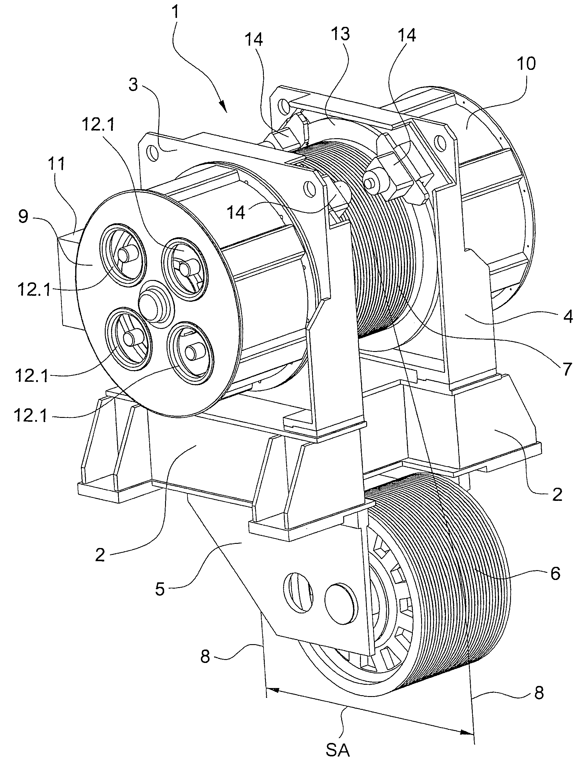
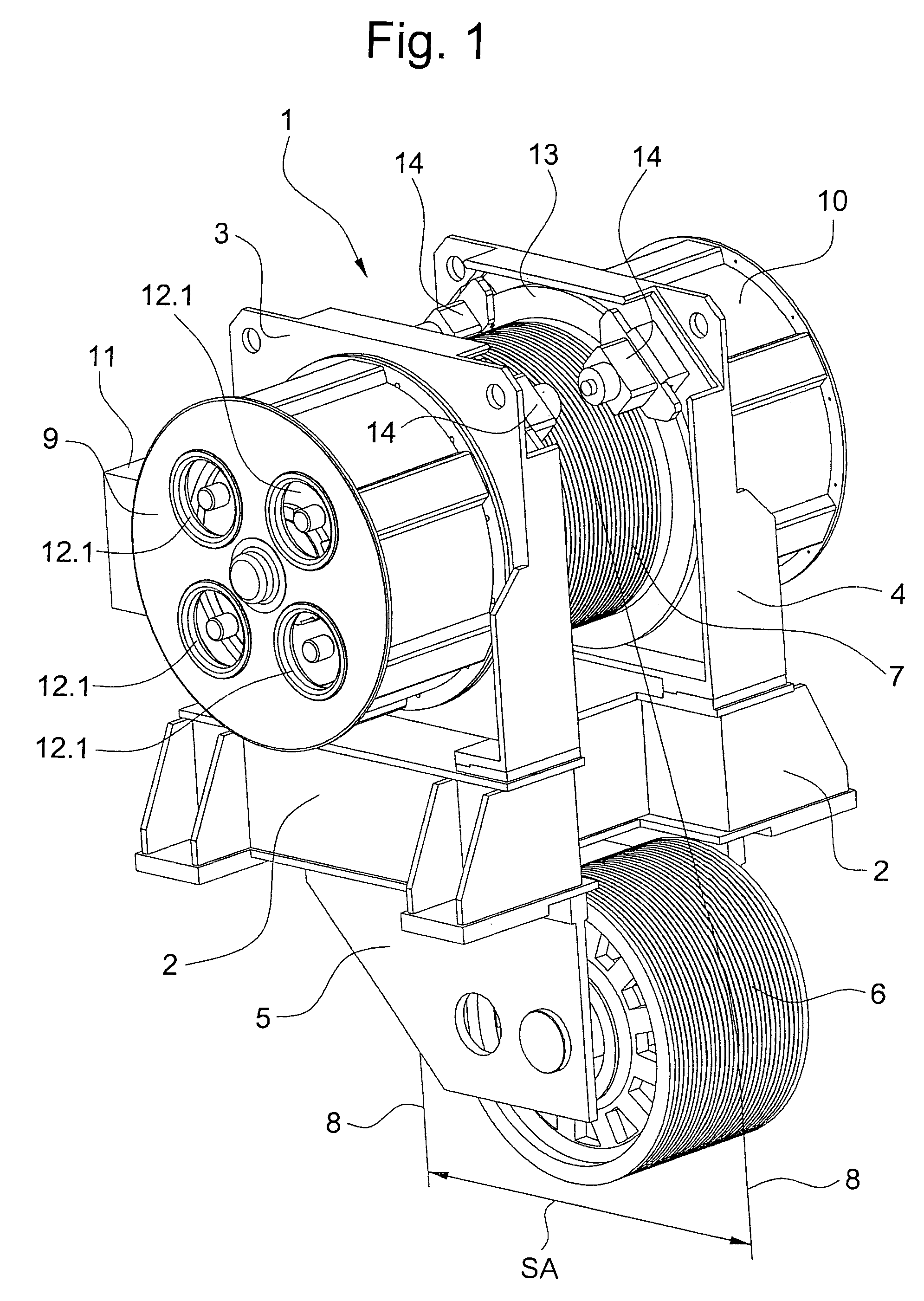
[0010]FIG. 1 shows a completely assembled drive unit 1, consisting essentially of a machine frame 2 on which a first bearing end-plate 3 and a second bearing end-plate 4 are arranged. Also arranged on the machine frame 2 is a secondary-sheave mounting 5 with a secondary sheave 6. The bearing end-plates 3, 4 support a traction sheave 7 over which ropes 8 are guided, the ropes 8 being also guided over the secondary sheave 6. A distance SA is required between the rope-fall of an elevator car (not shown) and a counterweight (not shown).

[0011]Arranged on the first bearing end-plate 3 is a first motor 9, and on the second bearing end-plate 4 a second motor 10. Each of the motors 9, 10 is provided with a terminal box 11 and with fans 12.1, 12.2 (FIG. 2). The traction sheave 7 has on each side a brake disk 13 on which two disk brakes 14 act.

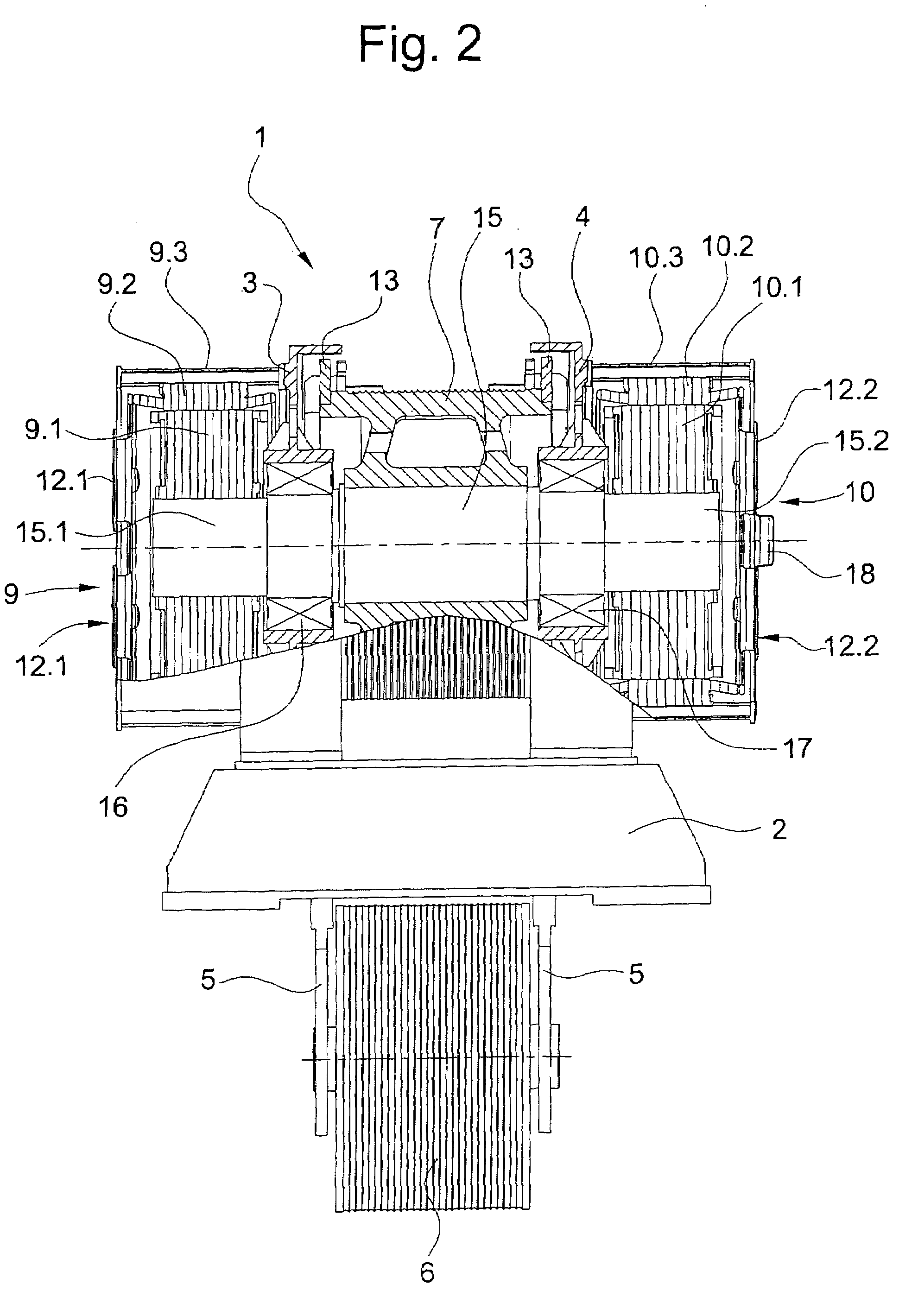
[0012]FIG. 2 shows a cross-section through the drive unit 1. The traction sheave 7 is supported by a shaft 15, the shaft 15 being held rotatably in a fi...


PUM


Abstract

An elevator drive unit including a traction sheave supported by a shaft rotatably supported by a pair of bearings. Mounted on opposite free ends of the shaft are rotors of a pair of electric motors. Cage-housings on a pair of spaced bearing end-plates retain the stators of the motors. A plurality of frequency converters operating in a master/slave mode to supply electrical power to the motors.

Description

BACKGROUND OF THE INVENTION[0001]The present invention relates to a drive unit for an elevator comprising motors and a traction sheave wherein the traction sheave and the motors are supported on bearing end-plates arranged on a machine frame.[0002]There is shown in the European patent application EP 0 565 893 a drive unit for elevators which, between two bearing end-plates, has a traction sheave and electric motors which can be mechanically coupled in series. The rigidly series-coupled external-rotor motors are synchronized by means of a multi-motor speed control. The traction sheave and the motors are supported on a rigid axle supported by the bearing end-plates.[0003]A disadvantage of this known device is that the forces acting on the rigid axle are unfavorably distributed. The main forces emanating from the traction sheave must largely be absorbed by the bearing end-plate. Also, the series-coupled electric motors make large distances between bearing end-plates necessary.SUMMARY O...

Claims


Application Information

Patent Timeline
IPC IPC(8): B66B1/06B66B11/08H02P7/00B66B11/04H02K7/10H02K7/14H02K16/00
CPCB66B11/043B66B11/0438H02K16/00H02K7/14H02K7/1004
Inventor AMMON, URSCHOLINSKI, ANDRZEJLUTHI, CHRISTIAN
Owner INVENTIO AG
Why Eureka
Try Eureka