Vehicle internal combustion engine

Inactive Publication Date: 2010-09-30
HONDA MOTOR CO LTD
View PDF7 Cites 4 Cited by
  • Summary
  • Abstract
  • Description
  • Claims
  • Application Information

AI Technical Summary

Benefits of technology

[0016]According to an embodiment of the present invention, the main shaft is disposed rearward of the crankshaft and the counter shaft is disposed rearward of the main shaft so that the crankshaft, the main shaft and the counter shaft are disposed from the front to the back in this order. Therefore, the vertical length of the crankcase can be made short. In addition, since the output shaft is disposed forward of and below the counter shaft, the anteroposterior length of the crankcase can be made short. Thus, the internal combustion engine can be downsized. The anteroposterior length of the crankcase is made short to shorten e.g. the wheelbase. Thus, the vehicle can be made compact and the turning performance of the vehicle can be enhanced.
[0017]The crankcase includes the vertically halved upper and lower case members and the main shaft and the counter shaft are disposed on the mating surface between the upper and lower case members. Therefore, the bearing structure of the main shaft and of the counter shaft can be simplified so that the assembly of the main shaft and of the counter shaft is facilitated.
[0018]The shift drum adapted to switch the combination of the gears on the main shaft and the counter shaft is disposed above and between the main shaft and the counter shaft. Th

Problems solved by technology

However, in the conventional configuration described above, the main shaft-side driven gears secured to the main shaft have ve

Method used


Image

  • Vehicle internal combustion engine
  • Vehicle internal combustion engine
  • Vehicle internal combustion engine

Examples


Example

[0026]A preferred embodiment of the present invention will hereinafter be described with reference to the drawings.

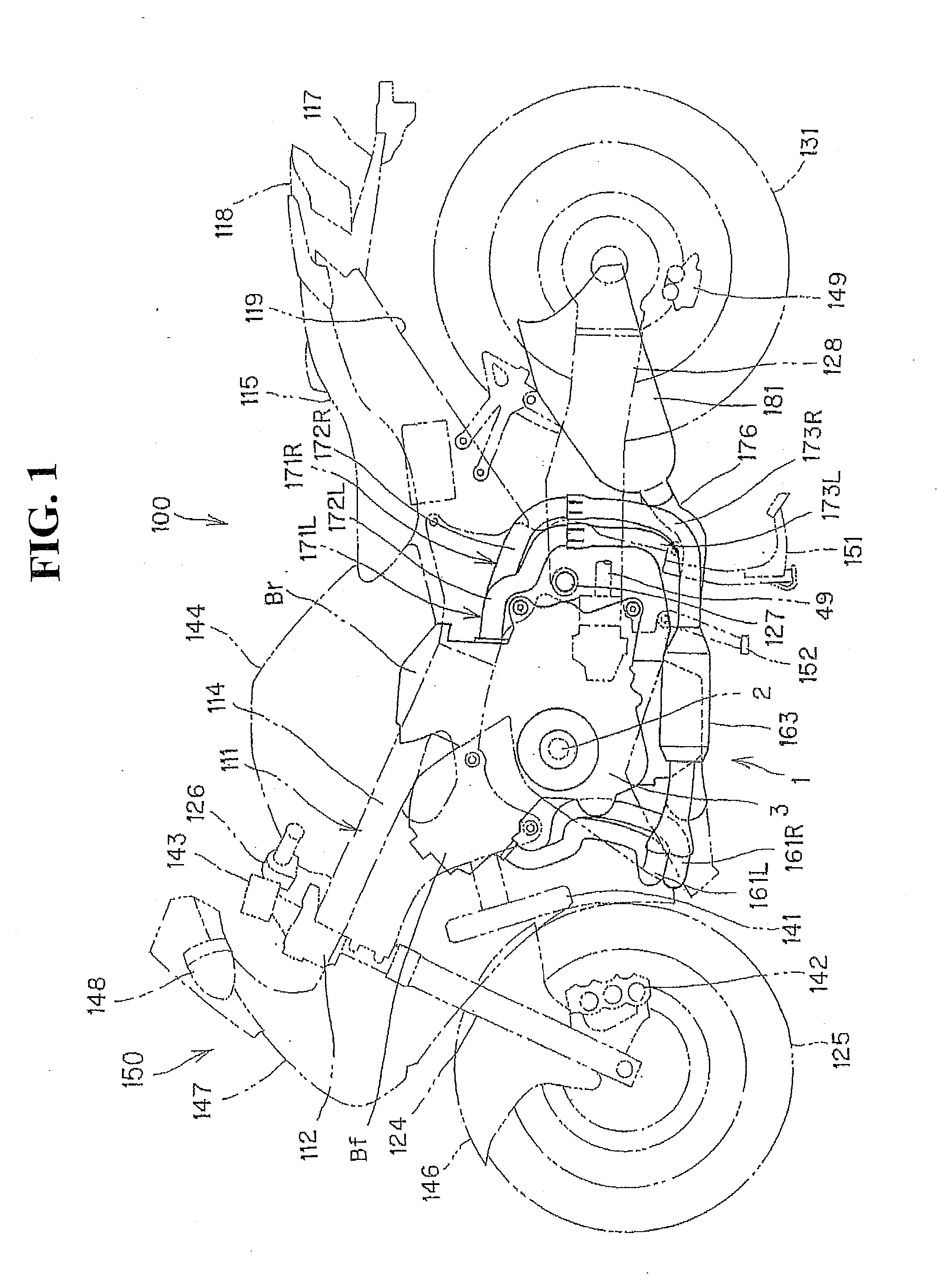
[0027]FIG. 1 is a lateral view of a motorcycle on which an internal combustion engine according to the embodiment of the present invention is mounted. In the following explanation, the descriptions of directions such as the front, rear, left, right, upside and downside are based on the direction of a vehicle body.

[0028]A body frame 111 of a motorcycle 100 includes a head pipe 112 located in a front portion of a vehicle body; main frames 114 extending rearwardly from the head pipe 112 to the center of the vehicle body; and rear frames (not illustrated) extending from rear ends of the main frames 114 to a rear portion of the vehicle.

[0029]A front fork 124 is turnably coupled to the head pipe 112. A front wheel 125 is rotatably supported by the lower end of the front fork 124. A steering handlebar 126 is mounted to the upper portion of the head pipe 112. In FIG. 1, a front...


PUM


Abstract

A vehicle internal combustion engine wherein the vertical length of a crankcase is made short in addition to making short the anteroposterior length of the crankcase. A vehicle internal combustion engine is configured such that a crankshaft, a main shaft, a counter shaft and an output shaft are arranged in parallel in a crankcase with the main shaft being disposed to the rear of the crankshaft and the counter shaft is disposed to the rear of the main shaft. The output shaft is disposed below and forward of the counter shaft.

Description

CROSS-REFERENCE TO RELATED APPLICATIONS[0001]The present application claims priority under 35 USC 119 to Japanese Patent Application No. 2009-087282 filed on Mar. 31, 2009 the entire contents of which are hereby incorporated by reference.BACKGROUND OF THE INVENTION[0002]1. Field of the Invention[0003]The present invention relates to a vehicle internal combustion engine having a crankshaft, a main shaft, a counter shaft and an output shaft arranged in parallel.[0004]2. Description of Background Art[0005]An internal combustion engine is known wherein a crankshaft, a main shaft, a counter shaft and an output shaft are arranged in parallel in a crankcase vertically halved into an upper case member and a lower case member. In this vehicle internal combustion engine, the crankshaft is provided at a mating surface of the crankcase. The main shaft is disposed vehicle-rearward of the crankshaft and above the mating surface of the crankcase. Main shaft-side driven gears, adapted to receive th...

Claims


Application Information

Patent Timeline
IPC IPC(8): F02B75/22F02F7/00
CPCF02B61/02F02B67/04Y02T10/148F16H57/02F16H2057/0203F02B75/22Y02T10/12
Inventor TERADA, KOJINAKAMURA, KENICHIRO
Owner HONDA MOTOR CO LTD
Why Eureka
Try Eureka