Eureka AIR delivers breakthrough ideas for toughest innovation challenges, trusted by R&D personnel around the world.

Sight Capable of Measuring Distance

Active Publication Date: 2017-02-02
SINTAI OPTICAL SHENZHEN CO LTD +1
View PDF5 Cites 4 Cited by
  • Summary
  • Abstract
  • Description
  • Claims
  • Application Information

AI Technical Summary

Benefits of technology

The invention provides a sight that can measure distance, and it is smaller, lighter, and more compact than previous designs. The sight includes a telescope, a laser transmitting module, a mount for adjusting elevation and windage, and a power supply. The telescope has a fixed reticle and no turrets to adjust elevation and windage. The mount for adjusting elevation and windage has a mounting part, an elevation adjusting part, and a windage adjusting part. The telescope focuses laser beams reflected from a target. The laser transmitting module includes a laser source and a collimating lens set. The mounting part has rods, knobs, and bayonets for easy mounting on a weapon. The windage adjusting part has forks, a spiral screw, and a limiting column, while the elevation adjusting part has a cylinder and a nut for movement in two directions. The technical effects of this invention include improved accuracy, reduced size, and ease of use for measuring distance.

Problems solved by technology

People estimate the distance of the target based on people's experience of seeing through the conventional sight, but the distance estimation is not accurate and results in missing the target.
Therefore, the solution of simply combing two individual sight and rangefinder together will result in big and heavy equipment.
As a result, it is very inconvenient to use the conventional combination.

Method used


Image

  • Sight Capable of Measuring Distance
  • Sight Capable of Measuring Distance
  • Sight Capable of Measuring Distance

Examples


Embodiment Construction

[0029]The following description is a preferable-contemplated mode of carrying out the invention. This description is made for the purpose of illustrating the general principles of the invention and should not be taken in a limiting sense. The scope of the invention is best determined by reference to the appended claims.

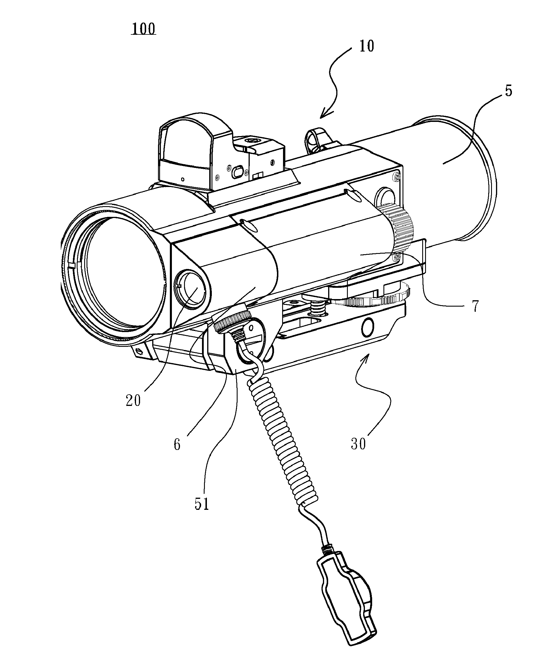
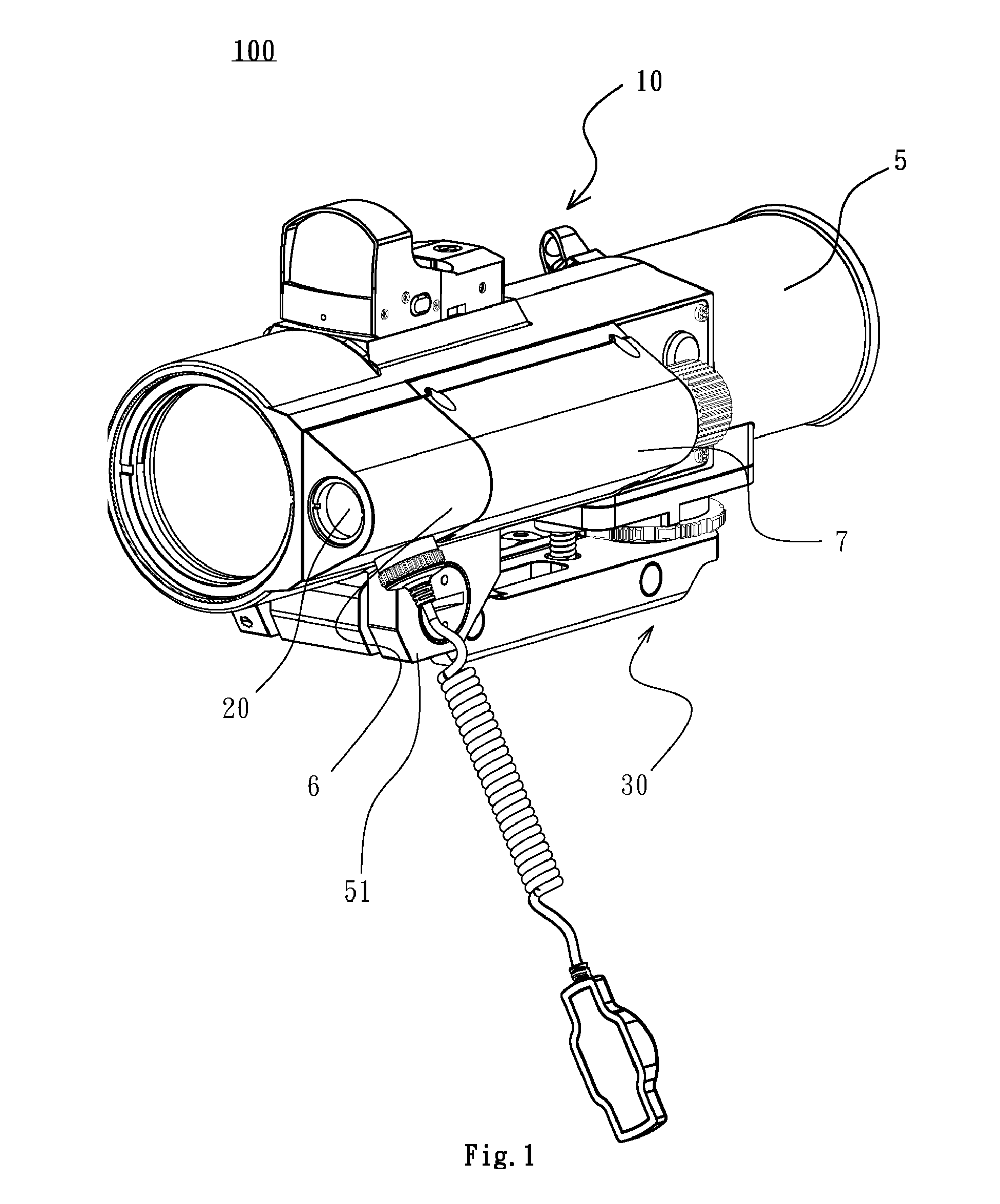
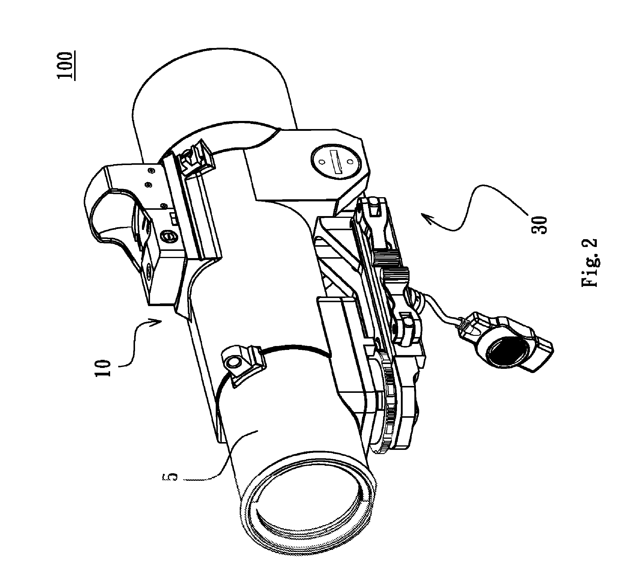
[0030]Referring to FIGS. 1 and 2, a sight 100 capable of measuring distance comprises a telescope 10, a laser transmitting module 20, and a mount for adjusting elevation and windage 30. The telescope 10 includes a barrel 5. The laser transmitting module 20 installed in a second housing 6, and the second housing 6 is steadfastly fixed on the outer barrel 5 of the telescope 10. A third housing 7 is steadfastly fixed on the outer barrel 5 of the telescope 10, and a power supply 40 (FIG. 4) is installed in the third housing 7. The power supply 40 connects electrically to the telescope 10 and the laser transmitting module 20 so as to supply power to the telescope 10 and th...


PUM


Abstract

A sight capable of measuring distance comprises a telescope without any turrets, a laser transmitting module, a mount for adjusting elevation and windage and a power supply. The telescope comprises a barrel, an unadjustable reticle fixed in the barrel and a laser receiving module fixed in the barrel. The laser transmitting module is steadfastly fixed on the outer barrel of the telescope and emitting a laser beam toward the target. The mount for adjusting elevation and windage is fixed on a lower side of the outer barrel of telescope, and comprises a mounting part, an elevation adjusting part and a windage adjusting part. The power supply electrically connects to the laser transmitting module and the laser receiving module.

Description

CROSS REFERENCE TO RELATED APPLICATIONS[0001]This application is a continuation-in-part application of U.S. patent application Ser. No. 14 / 818,341, “Sight capable of Measuring Distance”, filed on Aug. 5, 2015, which claims priority to Taiwan Patent Application No. 103127652, filed Aug. 12, 2014, all of which are incorporated herein by reference in its entirety.BACKGROUND OF THE INVENTION[0002]Field of the Invention[0003]The invention relates to a sight which is capable of measuring distance, and more particularly to a compact sight capable of measuring distance precisely without using any turrets.[0004]Description of the Related Art[0005]When using a gun to fire, people usually use a sight to aim a target. When aiming a target by using a conventional sight, people usually adjust elevation and windage to correct a bullet impact point according to a distance of the target and conditions of climate. People estimate the distance of the target based on people's experience of seeing throu...

Claims


Application Information

Patent Timeline
IPC IPC(8): F41G3/06F41G3/08F41G1/387F41G1/35
CPCF41G3/065F41G1/387F41G3/08F41G1/35F41G11/003F41G1/473
Inventor LIANG, SHANG-YUNG
Owner SINTAI OPTICAL SHENZHEN CO LTD
Why Eureka
Eureka Blog
Learn More