Multiple-needle suturing assembly

Inactive Publication Date: 2017-03-02
THD
View PDF7 Cites 0 Cited by
  • Summary
  • Abstract
  • Description
  • Claims
  • Application Information

AI Technical Summary

Benefits of technology

[0018]There is also provided in accordance with an embodiment of the present invention a method for suturing including providing a first puncture element including a sharp distal end for puncturing tissue, providing a second puncture element including a sharp distal end for puncturing tissue, the distal ends of the first and second puncture elements being spaced from each other by a gap, providing suture thread disposed along a portion of the first puncture element, wherein the suture thread is arranged to be grabbed at the distal end of the first puncture element, providing a suture grabber positioned at the distal end of the second puncture element, puncturing through a tissue wall with the first puncture element so that the suture thread passes from a near side of the tissue wall to a far side of the tissue wall, puncturing through the tissue wall with the second puncture element from the near side of the tissue wall to the far side of the tissue wall, and grabbing the suture thread with the suture grabber at the distal end of the first puncture element at the far side of the tissue wall, bringing the suture thread across the gap and moving the suture thread proximally away from the distal end of the second puncture element back through to the near side of the tissue wall. Afterwards, the suture thread may be secured to form a stitch.

Problems solved by technology

However, in endoscopic procedures, where access to the work site is not readily available, the surgeon must use auxiliary devices to be able to grasp the suture strands and pass them through desired tissue.

Method used


Image

  • Multiple-needle suturing assembly
  • Multiple-needle suturing assembly
  • Multiple-needle suturing assembly

Examples


Embodiment Construction

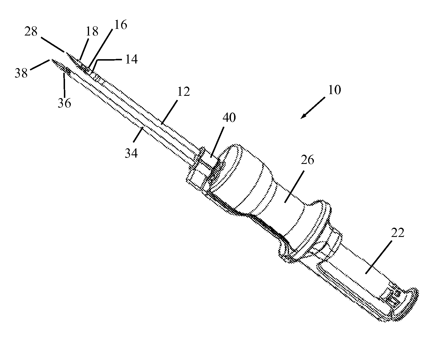
[0025]Reference is now made to FIG. 1, which illustrates a suturing assembly 10, constructed and operative in accordance with a non-limiting embodiment of the present invention.

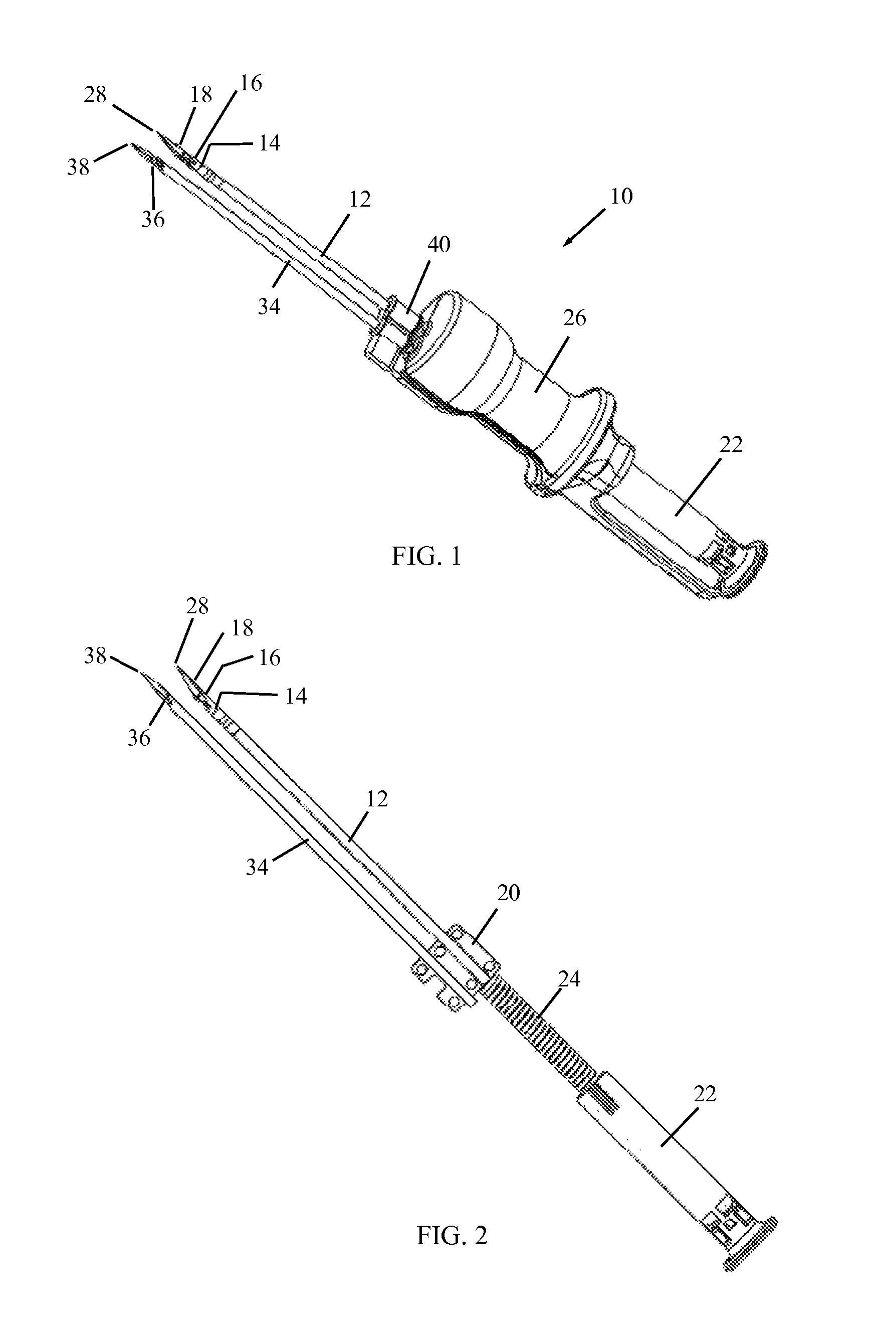
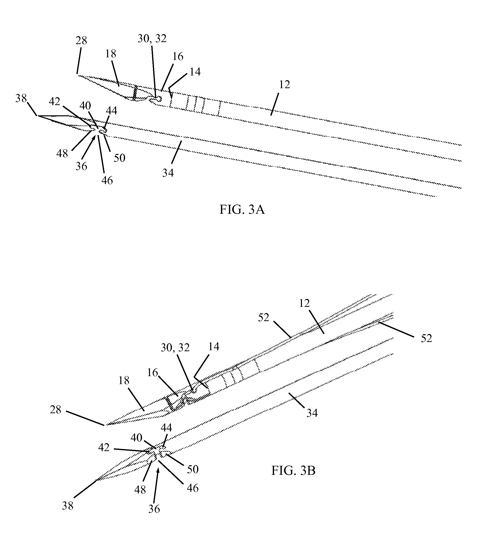
[0026]The suturing assembly 10 includes a suture passing member 12, which is formed with a lumen 14. A suture holding element 16 and a first puncture element 18 are disposed in lumen 14. As seen in FIG. 2, the proximal ends of suture passing member 12, that is, the proximal ends of suture holding element 16 and first puncture element 18, pass through or are attached to a mounting member 20 and are secured to a pushing member 22. A biasing device 24, such as a coil spring, is positioned between mounting member 20 and pushing member 22. The action of pressing on the pushing member 22 compresses biasing device 24 and advances the distal ends of suture holding element 16 and first puncture element 18 further away from the distal end of lumen 14. As seen in FIG. 1, a handle 26 is provided that encloses the mountin...


PUM


Abstract

A suturing assembly includes a suture passing member formed with a lumen in which are disposed a suture holding element and a first puncture element. Both the first puncture element and the suture holding element include suture receiving portions. A second puncture element includes a suture receiving portion. The first puncture element and the suture holding element have a retracted position and a deployed position. In the deployed position, the distal end of the first puncture element and/or suture holding element bends and passes over the distal end of the second puncture element, and a space is formed between the first puncture element and the suture holding element. During movement from the deployed position back to the retracted position, the suture receiving portion of the first puncture element and/or suture holding element moves adjacent the suture receiving portion of the second puncture element.

Description

FIELD OF THE INVENTION[0001]The present invention relates generally to suturing devices and methods, such as for the percutaneous closure of body lumens and tissues by means of sutures, and particularly to a suturing assembly with a bendable needle.BACKGROUND OF THE INVENTION[0002]Many suturing devices are known in the art that puncture the skin with needles and percutaneously deliver sutures to the site. However, in endoscopic procedures, where access to the work site is not readily available, the surgeon must use auxiliary devices to be able to grasp the suture strands and pass them through desired tissue.[0003]U.S. Pat. No. 7,842,050 describes a suture passing device which can advance, retract, and / or snare suture strands. The device incorporates superelastic puncturing components that exhibit superelastic properties such that they can be compressed into a straightening tube or integrated lumen of a device having a substantially smaller profile during deployment. The superelastic...

Claims


Application Information

Patent Timeline
Patent Type & Authority Applications(United States)
IPC IPC(8): A61B17/04
CPCA61B2017/0472A61B17/0469A61B2017/00867A61B2017/06019A61B2017/06042A61B17/0485
Inventor ALTMAN, NIR
Owner THD
Why Eureka
Try Eureka