

Pad and supporter
a technology which is applied in the field of supporter and pad, can solve the problems of inability to produce effective pads for pressing up against the arch, inflammation of the plantar fascia, and inability to produce pads equipped with pads, etc., and achieve the effect of curbing the fall of the plantar arch
- Summary
- Abstract
- Description
- Claims
- Application Information
AI Technical Summary
Benefits of technology
Problems solved by technology
Method used
Image

Examples
embodiment 1
[0029]The following description will discuss an embodiment of the present invention with reference to FIGS. 1 to 6. The present embodiment will describe an example supporter that includes a pad in accordance with the present invention.
[0030][Configuration of Supporter 100]
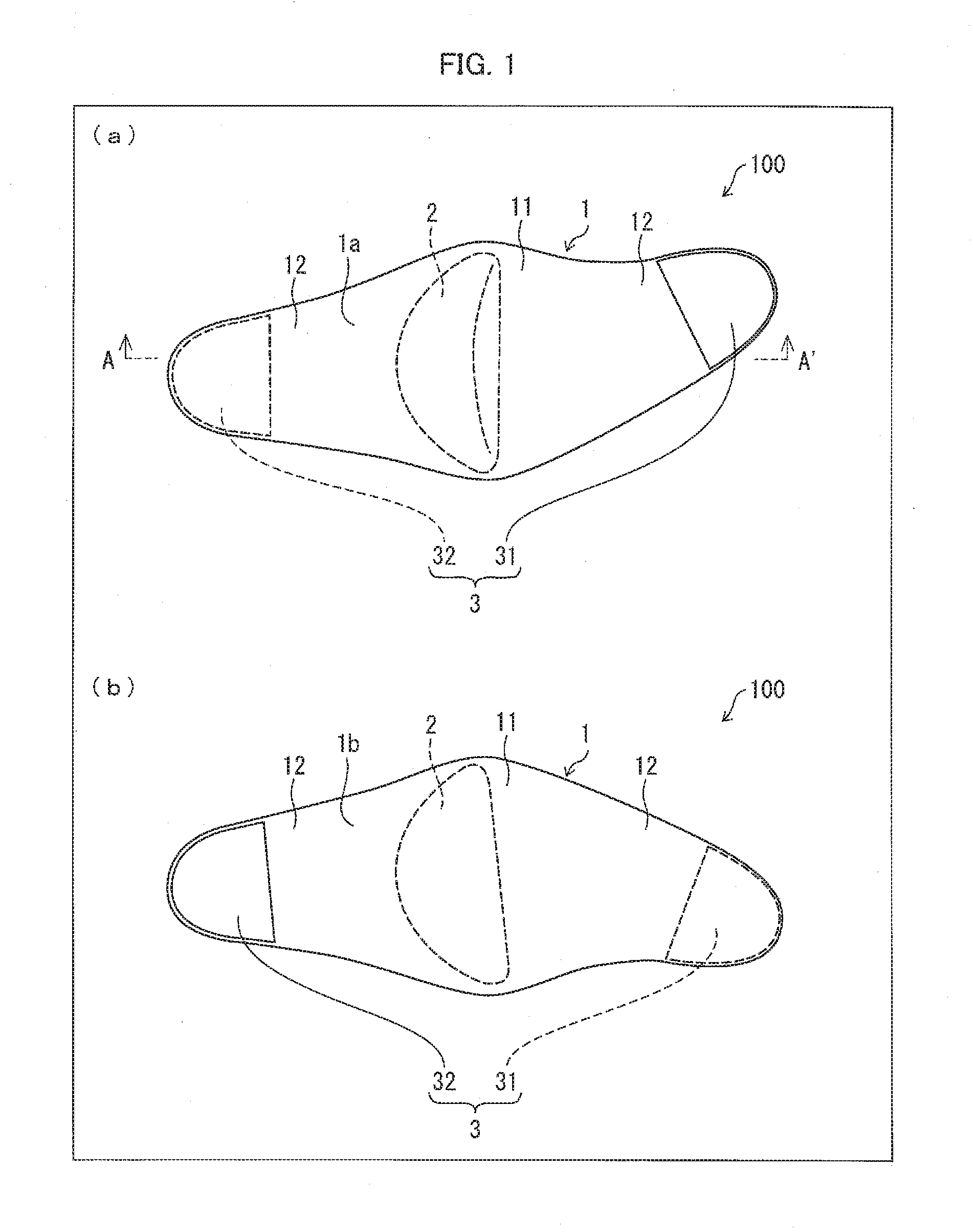
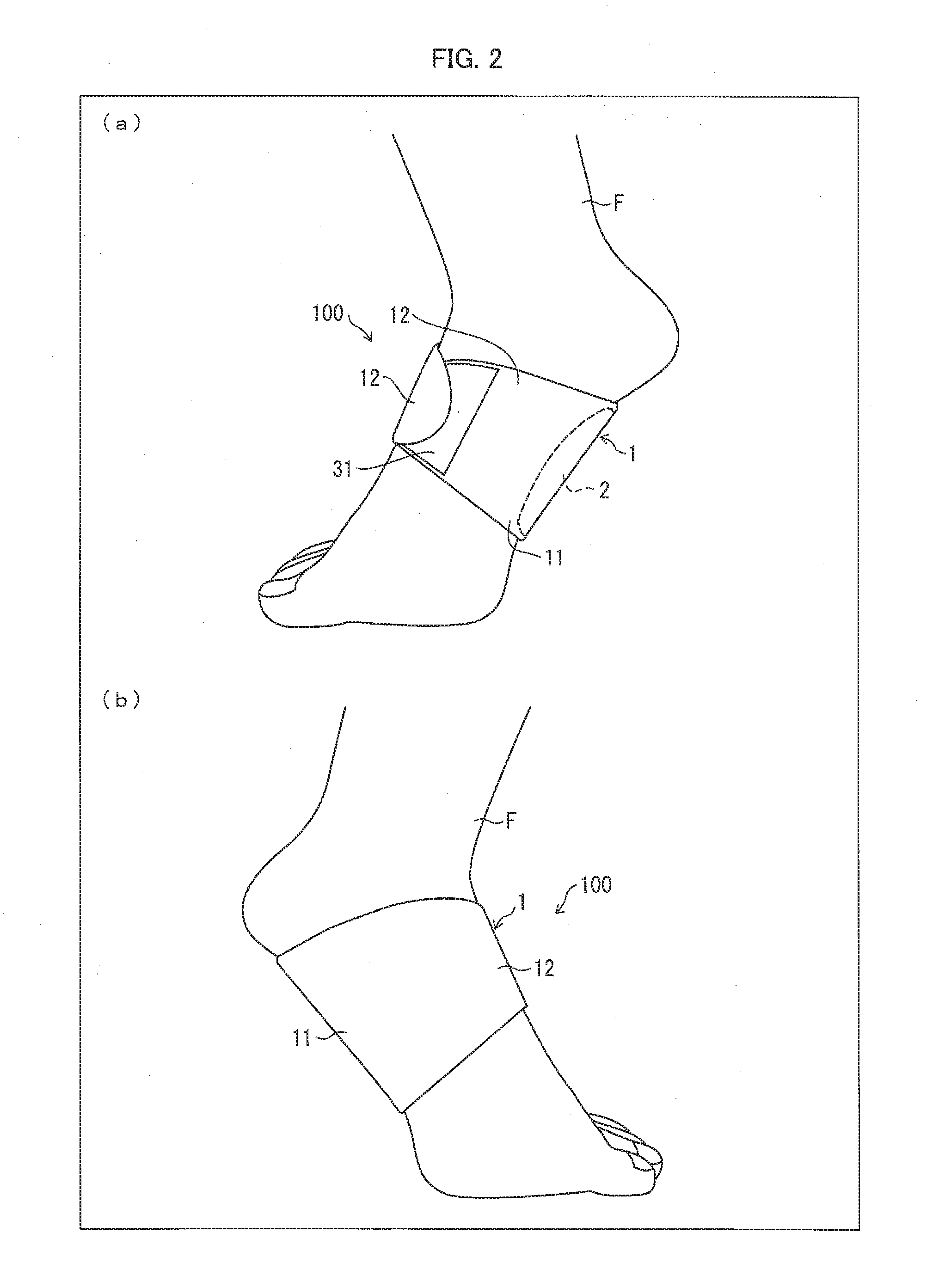
[0031]FIG. 1 is a plan view illustrating a supporter 100 in accordance with the present embodiment. (a) of FIG. 1 illustrates a back surface 1a side of the supporter 100, and (b) of FIG. 1 illustrates a front surface 1b side of the supporter 100. FIG. 2 is a side view of the supporter 100 illustrated in FIG. 1 in a state of being worn by a foot (right foot) F. (a) of FIG. 2 illustrates a state of the supporter 100 when viewed from a medial side of the foot F, and (b) of FIG. 2 illustrates a state of the supporter 100 when viewed from a lateral side of the foot F.
[0032]The supporter 100 in accordance with the present embodiment has a pad 2 that supports a plantar arch of a sole of the foot F when the supporter 100 i...
embodiment 2
[0076]The following description will discuss another embodiment of the present invention with reference to FIGS. 7 and 8. The present embodiment will describe another example supporter that includes a pad in accordance with the present invention.
[0077]For convenience of explanation, members having the same functions as those described in the aforementioned embodiment are given the same reference numerals, and are not described here.
[0078][Configuration of Supporter 101]
[0079]FIG. 7 is a plan view illustrating a supporter 101 in accordance with the present embodiment. (a) of FIG. 7 illustrates a back surface 1a side of the supporter 101, and (b) of FIG. 7 illustrates a front surface 1b side of the supporter 101. FIG. 8 is a side view of the supporter 101 illustrated in FIG. 7 in a state of being worn by a foot (right foot) F. (a) of FIG. 8 illustrates a state of the supporter 101 when viewed from a medial side of the foot F, and (b) of FIG. 8 illustrates a state of the supporter 101 ...
embodiment 3
[0090]The following description will discuss still another embodiment of the present invention with reference to FIGS. 9 and 10. The present embodiment will describe still another example supporter that includes a pad in accordance with the present invention.
[0091]For convenience of explanation, members having the same functions as those described in the aforementioned embodiments are given the same reference numerals, and are not described here.
[0092][Configuration of Supporter 102]
[0093]FIG. 9 is an external view of a supporter 102 in accordance with the present embodiment. FIG. 10 is a side view of the supporter 102 illustrated in FIG. 9 in a state of being worn by a foot (right foot) F. (a) of FIG. 10 illustrates a state of the supporter 102 when viewed from a medial side of the foot F, and (b) of FIG. 10 illustrates a state of the supporter 102 when viewed from a lateral side of the foot F.
[0094]As illustrated in FIGS. 9 and 10, the supporter 102 includes a main body part 61 an...
PUM
 Abstract
Description
Claims
Application Information