Bottle Neck Insert for Inhibiting Spillage or Accidental Exposure, and Related Methods and Systems

a bottle neck and insert technology, applied in the field of devices, systems and methods for inhibiting spillage or accidental exposure of the contents of bottles and packaging, can solve the problems of no mechanism, no existing mechanism which serves the purpose of physical barrier, and bottles with uneven interior surfaces

Inactive Publication Date: 2017-03-09
PUREBACCO USA LLC
View PDF6 Cites 3 Cited by
  • Summary
  • Abstract
  • Description
  • Claims
  • Application Information

AI Technical Summary

Problems solved by technology

Traditional “Boston Round” glass bottles having smooth interior surfaces in the neck region with removable childproof droppers have no mechanism to prevent spillage or drinking once the dropper is removed.
These bottles often contain concentrated essential oils, or e-liquids (nicotine liquids) which require child safe packaging; however, even with approved industry leading child safety safeguards in place, once the

Method used


Image

  • Bottle Neck Insert for Inhibiting Spillage or Accidental Exposure, and Related Methods and Systems
  • Bottle Neck Insert for Inhibiting Spillage or Accidental Exposure, and Related Methods and Systems
  • Bottle Neck Insert for Inhibiting Spillage or Accidental Exposure, and Related Methods and Systems

Examples


second embodiment

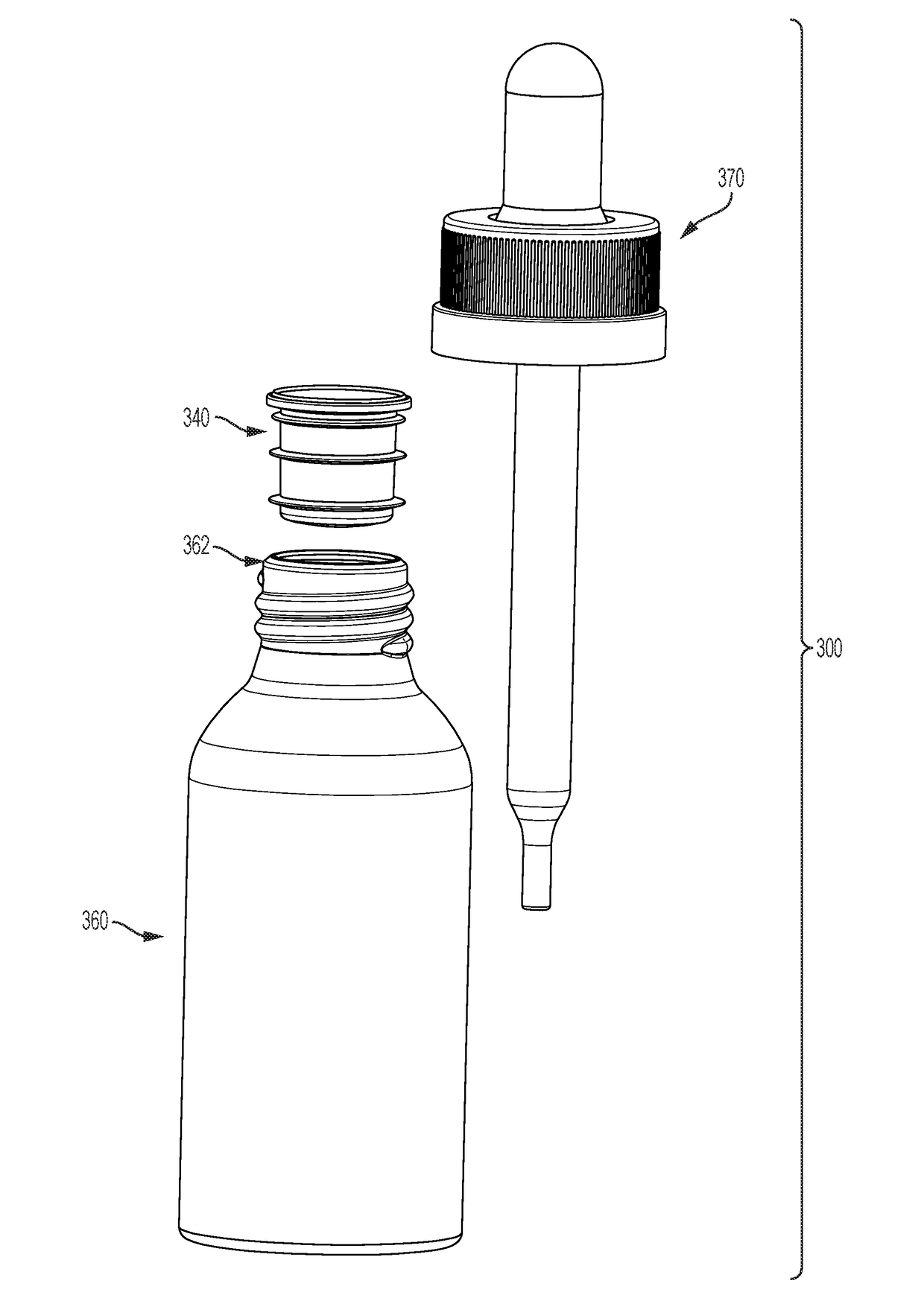
[0071]FIG. 12A contrasts this with the second embodiment Locking Spill Inhibitor Unit 340 which utilizes Mated Collar-Locking Ring 344 which mates to Bottle Neck Locking Chime 362 to produce a Mated Locking effect with the flange located on the inside of the bottle neck. See FIG. 15A. The mated collar-locking ring 344 can be in a range of about 1 mm to about 3.5 mm. The subsequent flange, Stability Ring 346, is then used to stabilize the unit with the Thread Stop Sealing Ring 348 serving to further secure the unit in place at the bottom of the bottle neck.

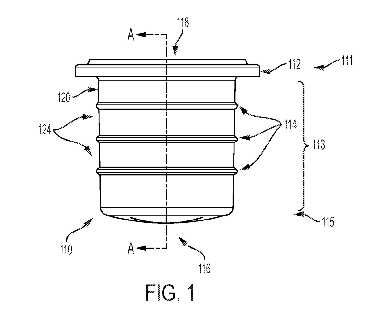
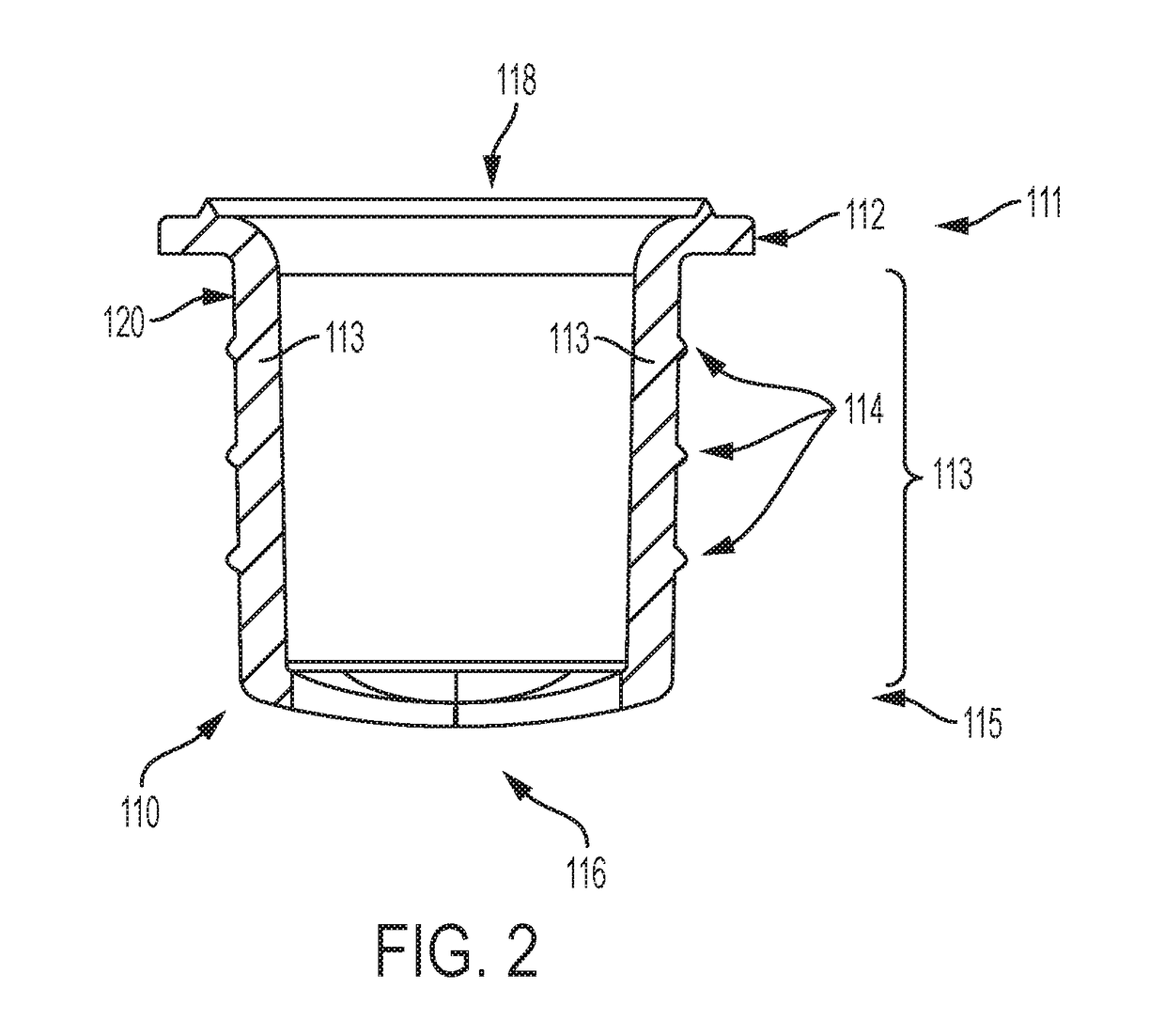
[0072]Contrast Explained: Both embodiments include three elevated rings, however, in the second embodiment Locking Spill Inhibitor Unit 340 these rings are significantly larger and provide Physical Surface to Surface locks in the bottle neck, made possible by a ring added to the internal side of the bottle. The rings of the locking spill inhibitor unit 340 can extend up to 2 mm from the cylindrical housing 341. The rings of the loc...

embodiment 2

[0073]FIG. 12B is a cross-section view of FIG. 12A. This embodiment can include a mated solution, although semi-universal in Embodiment 2 the Insert is mated to a specific bottle, and is thus variant dependent on the bottle it is being mated to. In this way, the rings and final length of the insert are variant within the confines of the embodiment. As long as the three rings are there, and they serve their three functions they can be individually variant based on the specific bottle they are mating to.

[0074]FIG. 13A shows a front / rear view of a bottle with insert in the neck, according to an embodiment of the invention.

[0075]FIG. 13B shows a cross-section view of FIG. 13A.

[0076]FIG. 13C shows an exploded perspective view of FIG. 13A.

[0077]FIG. 13D shows a top view of FIG. 13A.

[0078]FIG. 14A shows a front view of a bottle having an insert in the neck and a pipette inserted therein, according to an embodiment of the invention.

[0079]FIG. 14B shows a cross-section view of FIG. 14A.

[0080...


PUM


Abstract

A bottle neck insert can include a cylindrical body having a first end and a second end, the cylindrical body having a plurality of rings; a flange provided at the first end, the flange protruding outwardly from the cylindrical body in a radial direction of the cylindrical body; and a valve section at the second end, the valve section having at least one slit, wherein the flange is configured to seat the insert onto a neck of a bottle and the valve section is configured to allow a pipette to pass through. A bottle storage system, can include a bottle having a neck with a smooth interior surface; an insert that is configured to fit inside the neck of the bottle; and a pipette assembly that is configured to proceed through the insert into the bottle.

Description

CROSS-REFERENCE TO RELATED APPLICATIONS[0001]This application claims priority to U.S. Provisional Application No. 62 / 216,220, filed Sep. 9, 2015, the content of which is hereby incorporated herein in its entirety.TECHNICAL FIELD[0002]The present invention relates to devices, systems and methods for inhibiting spillage or accidental exposure of the contents of bottles and packaging.BACKGROUND[0003]Traditional “Boston Round” glass bottles having smooth interior surfaces in the neck region with removable childproof droppers have no mechanism to prevent spillage or drinking once the dropper is removed. These bottles often contain concentrated essential oils, or e-liquids (nicotine liquids) which require child safe packaging; however, even with approved industry leading child safety safeguards in place, once the dropper is removed, there is no existing mechanism which serves the purpose of a physical barrier for limiting spillage or accidental exposure.[0004]Further, bottles having inter...

Claims


Application Information

Patent Timeline
IPC IPC(8): B65D39/08B65D39/04B65D53/00B65D1/02
CPCB65D39/08B65D53/00B65D39/04B65D1/0246B01L3/50825B65D51/002B01L2300/044B01L2300/049
Inventor WALSH, MARK D.NEMEC, BRUCE C.ROHR, JASON R.
Owner PUREBACCO USA LLC
Why Eureka
Try Eureka