Appliance Shipping Runner

a technology for runners and runners, applied in the field of runners for applications, can solve the problems of insufficient localized stiffness of runners, difficulty in moving, and insufficient stiffness of runners, and achieve the effect of increasing stiffness

Active Publication Date: 2017-03-23
CUSTOM PAK
View PDF0 Cites 3 Cited by
  • Summary
  • Abstract
  • Description
  • Claims
  • Application Information

AI Technical Summary

Benefits of technology

[0009]It is therefore an object of the invention to provide a runner having attachment points with increased stiffness.

Problems solved by technology

Due to the weight and / or size of these items, they can be difficult to move.
The difficulty with currently available blow molded runners is that stiffness of the runner is often inadequate in the warehousing scenario when multiple bulky items, such as dishwashers are stacked on top of each other.
Although double walled configurations add bending stiffness over longer lengths, the thickness and / or configuration of the walls may provide insufficient localized stiffness.
The bulky item is often positioned on the runner at specific points, which results in point like loads or loads that are distributed over a relatively small portion of the runner.
In addition, the cross section may have a tendency to deform or bend away from the axis of the force.
The buckling and deformation problems around the mounting areas can create a situation in which the entire stack can shift and if the buckling is too much, there is the possibility that an appliance becomes damaged.

Method used


Image

  • Appliance Shipping Runner
  • Appliance Shipping Runner
  • Appliance Shipping Runner

Examples


Embodiment Construction

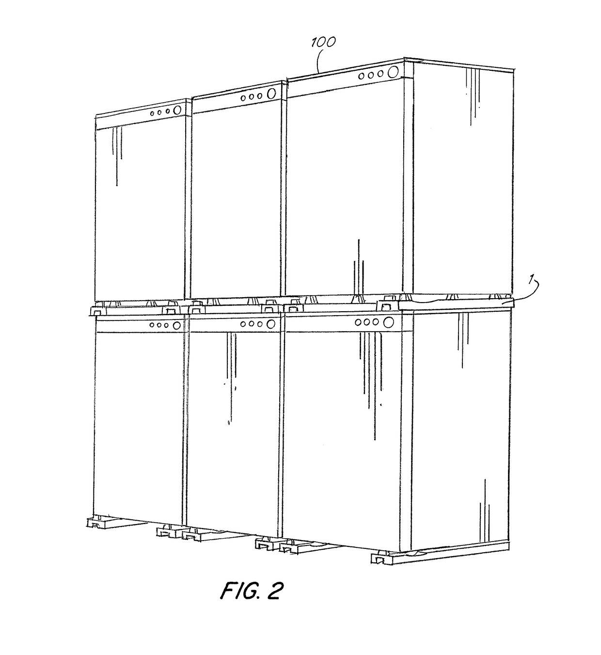
[0040]Referring now to the drawings, wherein like reference numerals designate corresponding structure throughout the views, the following examples are presented to further illustrate and explain the present invention and should not be taken as limiting in any regard. In FIG. 2, an example stack of appliances 100 is shown with runners 1 mounted to the bottom of the appliances 100. The runners 1 allow the appliances 100 to be slid along the floor of the warehouse or into packaging. On the bottom of the runners 1 there may be protrusions 30 which may reduce friction between the runner 1 and the surface the runner sits.

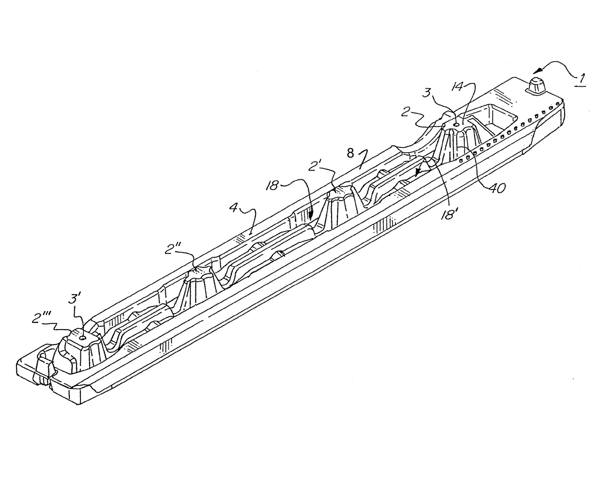
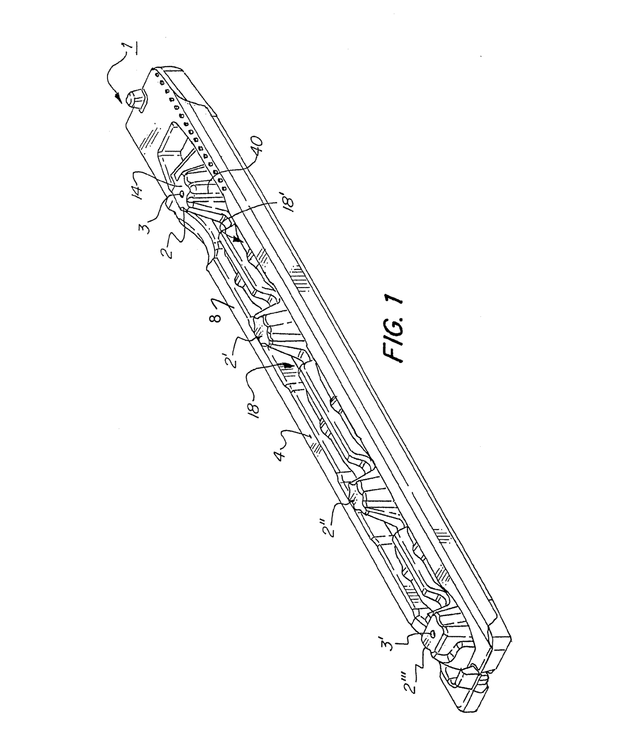
[0041]In FIGS. 1 and 3-8, the runner 1 is shown with four columns 2, 2′, 2″, 2′″. The outer columns 2 and 2′″ are shown with holes 3, 3′ therein. The holes can receive bolts or other types of securing structures to secure the runner 1 to an appliance or other item. The runner 1 includes a top wall 4 with a top surface 8 and a bottom wall 6 and a bottom surface 10. The ru...


PUM


Abstract

A blow molded runner having a bottom wall and a top wall forming a double wall blow molded configuration, at least one compressed double wall structure defined by fusion an inner surface of the bottom wall to an inner surface of the top wall. At least two columns spaced apart at a distance wherein each of the at least two columns defines one of the at least one compressed double wall structure and has a top surface and the compressed double wall structure corresponding to each of the at least two columns extends from the top surface to a bottom surface of the runner at the at least two columns wherein the bottom surface is defined by an outer surface of the bottom wall. A width of the runner varies along a length thereof.

Description

FIELD OF THE INVENTION[0001]This invention relates to items used in packaging, shipping and warehousing large, bulky items. More particularly, the invention relates to runners that are affixed to the bottom of appliances for warehousing, packaging and shipping purposes.BACKGROUND OF THE INVENTION[0002]Runners are commonly used when warehousing, shipping and packaging large, bulky items such as appliances. Due to the weight and / or size of these items, they can be difficult to move. In warehousing situations, the ability to slide these items into and out of packaging is desired to aid both in packing and un-packing of the bulky item. The advantages in unpacking are further provided in that installation is aided due to the ability of the runner to easily slide along a floor and make it easier to move the bulky item closer to the installation position.[0003]Runners mounted to the bottom of appliances also provide protection to the corners and edges of the appliance in that the runners e...

Claims


Application Information

Patent Timeline
Patent Type & Authority Applications(United States)
IPC IPC(8): F16M11/42B65D61/00B65D85/68F16M11/22
CPCF16M11/42F16M11/22F16M2200/08B65D85/68B65D61/00B65D67/00B65D71/70B65D85/20B65D85/66B65D2585/6855D06F39/001
Inventor MACHANDE, JOSHUAZIMMER, RONALD A.
Owner CUSTOM PAK
Why Eureka
Try Eureka