
Artificially rendering images using viewpoint interpolation and extrapolation

a viewpoint and image technology, applied in the field of artificial rendering images, can solve the problems of limiting the efficiency of these methods in processing speed and transfer rate, limiting the viewer's passive experience, and traditional digital media formats such as 2d flat images not easy to lend themselves to reproducing memories and events with high fidelity

Active Publication Date: 2017-03-23
FUSION
View PDF34 Cites 68 Cited by
  • Summary
  • Abstract
  • Description
  • Claims
  • Application Information

AI Technical Summary

Benefits of technology

The present invention relates to methods for creating artificially rendered images using viewpoint interpolation and extrapolation. These methods require less data and can process images faster and more efficiently than traditional methods. The invention also provides mechanisms for detecting and replacing missing data in the image. The technical effects of the invention include improved efficiency and accuracy in generating high-fidelity images with greater detail and realistic memories.

Problems solved by technology

Traditional digital media formats typically limit their viewers to a passive experience.
Accordingly, traditional digital media formats, such as 2D flat images, do not easily lend themselves to reproducing memories and events with high fidelity.
This limits the efficiency of these methods in processing speed as well as transfer rates when sending it over a network.

Method used


Image

  • Artificially rendering images using viewpoint interpolation and extrapolation
  • Artificially rendering images using viewpoint interpolation and extrapolation
  • Artificially rendering images using viewpoint interpolation and extrapolation

Examples


Embodiment Construction

[0019]Reference will now be made in detail to some specific examples of the invention including the best modes contemplated by the inventors for carrying out the invention. Examples of these specific embodiments are illustrated in the accompanying drawings. While the present disclosure is described in conjunction with these specific embodiments, it will be understood that it is not intended to limit the invention to the described embodiments. On the contrary, it is intended to cover alternatives, modifications, and equivalents as may be included within the spirit and scope of the invention as defined by the appended claims.

[0020]In the following description, numerous specific details are set forth in order to provide a thorough understanding of the present invention. Particular embodiments of the present invention may be implemented without some or all of these specific details. In other instances, well known process operations have not been described in detail in order not to unnec...


PUM


Abstract

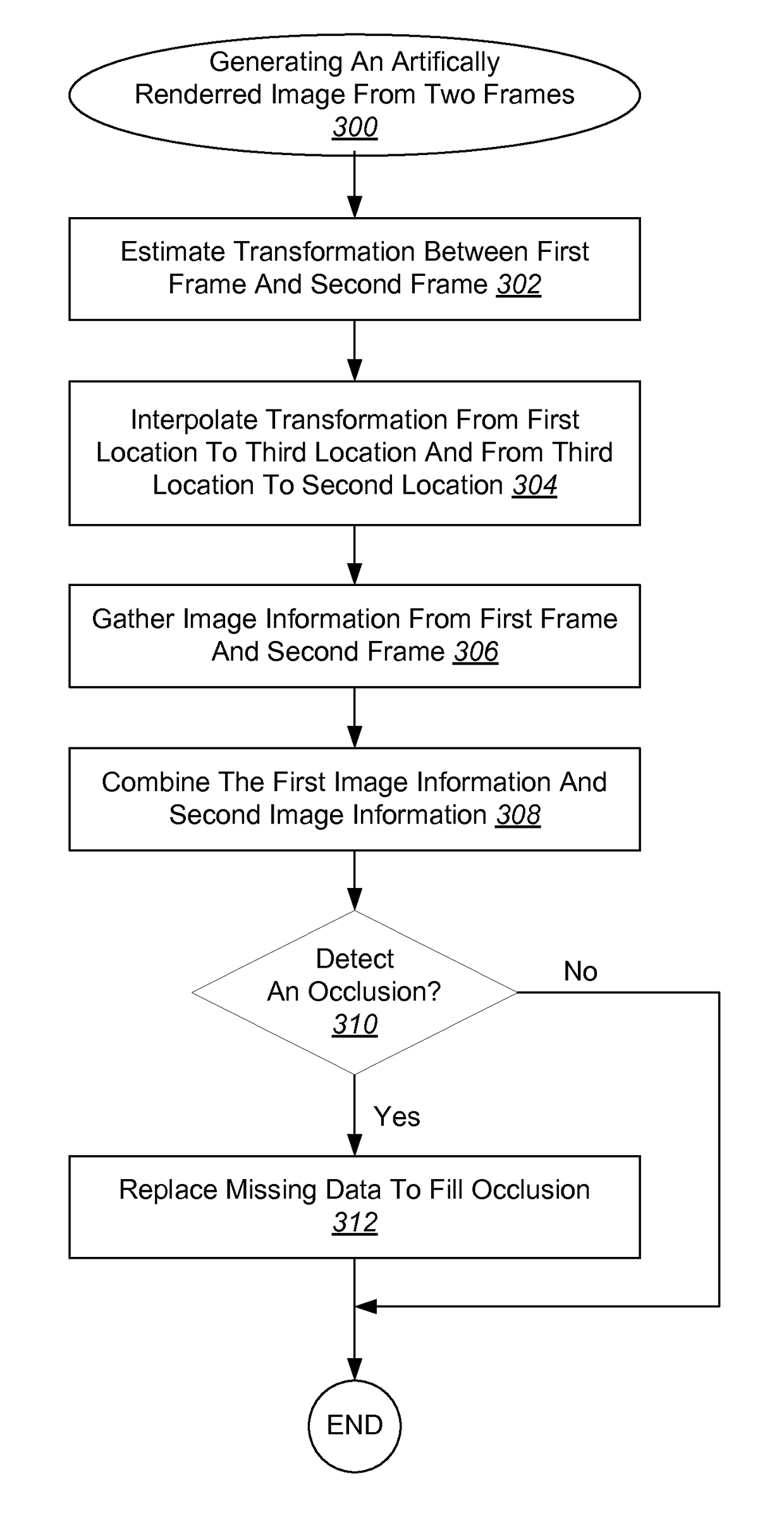
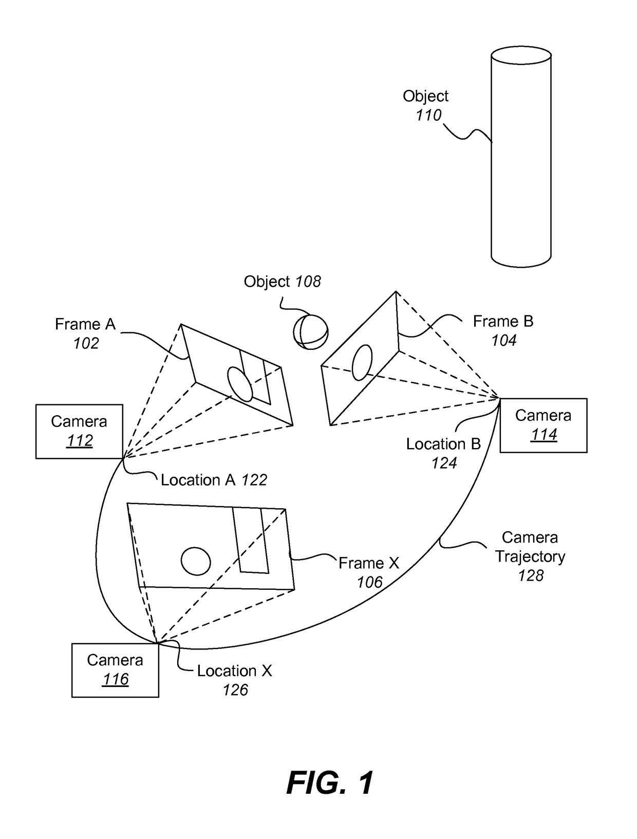
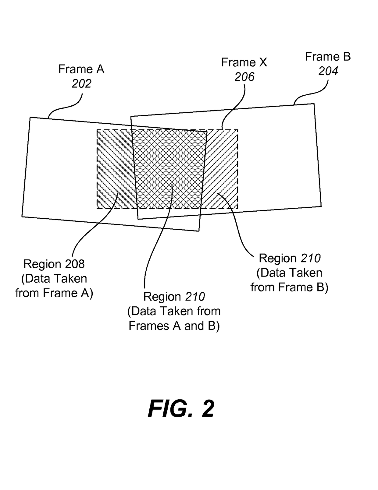
Various embodiments of the present invention relate generally to systems and methods for artificially rendering images using viewpoint interpolation and / or extrapolation. According to particular embodiments, a transformation between a first frame and a second frame is estimated, where the first frame includes a first image captured from a first location and the second frame includes a second image captured from a second location. An artificially rendered image corresponding to a third location positioned on a trajectory between the first location and the second location is then generated by interpolating a transformation from the first location to the third location and from the third location to the second location and gathering image information from the first frame and the second frame by transferring first image information from the first frame to the third frame based on the interpolated transformation and second image information from the second frame to the third frame based on the interpolated transformation. The first image information and the second image information are then combined. If an occlusion is created by a change in layer placement between the first frame and second frame, this occlusion is detected and missing data is replaced to fill the occlusion.

Description

TECHNICAL FIELD[0001]The present disclosure relates to artificially rendering images using viewpoint interpolation and / or extrapolation.DESCRIPTION OF RELATED ART[0002]With modern computing platforms and technologies shifting towards mobile and wearable devices that include camera sensors as native acquisition input streams, the desire to record and preserve moments digitally in a different form than more traditional two-dimensional (2D) flat images and videos has become more apparent. Traditional digital media formats typically limit their viewers to a passive experience. For instance, a 2D flat image can be viewed from one angle and is limited to zooming in and out. Accordingly, traditional digital media formats, such as 2D flat images, do not easily lend themselves to reproducing memories and events with high fidelity.[0003]Producing combined images, such as a panorama, or a three-dimensional (3D) image or model requires combining data from multiple images and can require interpo...

Claims


Application Information

Patent Timeline
Patent Type & Authority Applications(United States)
IPC IPC(8): G06T3/00G06T11/60
CPCG06T11/60G06T3/00H04N13/111G06T5/77
Inventor HOLZER, STEFAN JOHANNES JOSEFMILLER, STEPHEN DAVIDSAELZLE, MARTINRUSU, RADU BOGDAN
Owner FUSION
Learn More