Mobile terminal and method for controlling the same
What is AI technical title?
AI technical title is built by Patsnap AI team. It summarizes the technical point description of the patent document.
a mobile terminal and terminal technology, applied in the field of mobile terminals, to achieve the effect of slim configuration and high quality
Active Publication Date: 2017-03-23
LG ELECTRONICS INC
View PDF6 Cites 96 Cited by
Summary
Abstract
Description
Claims
Application Information
AI Technical Summary
This helps you quickly interpret patents by identifying the three key elements:
Problems solved by technology
Method used
Benefits of technology
Benefits of technology
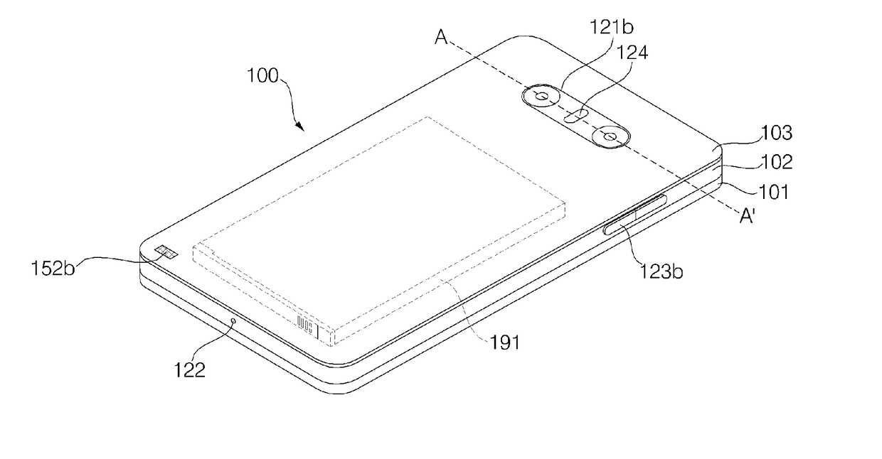
The present invention provides a novel mobile terminal with a dual camera module that can perform zoom-in / out functions, 3D scanning, and high quality optical images using two cameras with different fields of view. By aligning the first and second camera modules so that their fields of view coincide, the mobile terminal can capture images that have a wider field of view than the standard lens. The mobile terminal can display the captured images on its display unit for easy viewing and combining of images. The technical effects of the invention include improved image quality, zoom-in / out functions, and 3D scanning capabilities.
Problems solved by technology
Third, it may rapidly implement auto-focus and zoom functions.
Method used
Image
Click on the blue label to locate the original text in one second.
Reading with bidirectional positioning of images and text.
Examples
first embodiment
[0160]FIGS. 4 and 5 explain the configuration of a dual camera module in accordance with a first embodiment of the present disclosure.
[0161]Referring to FIGS. 4 and 5, a dual camera module 400 can include, for example, a first camera module 410, a second camera module 420, a camera sensor unit 430, a gyro sensor 440, first and second support members 450 and 460, and first to third fixing members 470 to 490.
[0162]First camera module 410 can include a standard lens assembly 411, an IR filter (not illustrated), an image sensor 413, and an AF driver (not illustrated). Standard lens assembly 411, used in first camera module 410, can have a conversion focal length of 43.27 mm and a field of view within a range of 60 degrees to 80 degrees. In addition, as a non-limiting embodiment, image sensor 413 used in first camera module 410 can have an aspect ratio of 16:9 and may include 16 mega pixels.
[0163]In an exemplary embodiment illustrated in FIG. 5(a), standard lens assembly 411 can have a c...
second embodiment
[0203]FIGS. 11 and 12 are diagrams referenced to explain the configuration of a dual camera module in accordance with a second embodiment of the present invention.
[0204]Referring to FIGS. 11 and 12, a dual camera module 1100 can include a first camera module 1110, a second camera module 1120, a camera sensor unit 1130, a gyro sensor 1140, first and second support members 1150 and 1160, and first to third fixing members 1170 to 1190.
[0205]First camera module 1110 can include a standard lens assembly 1111, an IR filter (not illustrated), an image sensor 1113, and an AF driver (not illustrated). In exemplary embodiments, standard lens assembly 1111 used in first camera module 1110 can have a conversion focal length of 43.27 mm and a field of view within a range from 60 degrees to 80 degrees. In a non-limiting exemplary embodiment, image sensor 1113 used in the first camera module 1110 can instead have an aspect ratio of 16:9 and may include 16 mega pixels.
[0206]In an exemplary embodime...
PUM
Abstract
Disclosed is a dual camera module equipped in a mobile terminal. The dual camera module includes a first camera module having a first focal length and a first field of view, a second camera module spaced apart from the first camera module by a predetermined distance, the second camera module having a second focal length and a second field of view, which are different from those of the first camera module, a sensor unit located in a space between the first camera module and the second camera module, and at least one member configured to align the first and second camera modules in a line so that beginning points of the fields of view of the first and second camera modules coincide with each other.
Description
CROSS-REFERENCE TO RELATED APPLICATION[0001]This application claims priority to Korean Patent Application No. 10-2015-0134084 filed on Sep. 22, 2015 in Korea, the entire contents of which is hereby incorporated by reference in its entirety.BACKGROUND OF THE DISCLOSURE[0002]1. Field of the Disclosure[0003]The present invention relates to a mobile terminal and a method for controlling the same, and more particularly, to a mobile terminal, which may provide a high performance image capture function based on dual cameras having different fields of view, and a method for controlling the same.[0004]2. Background of the Disclosure[0005]Terminals may be generally classified as mobile / portable terminals or stationary terminals according to their mobility. Mobile terminals may also be classified as handheld terminals or vehicle mounted terminals according to whether or not a user can directly carry the terminal.[0006]Mobile terminals have become increasingly more functional. Examples of such ...
Claims
Application Information
Patent Timeline
Application Date:The date an application was filed.
Publication Date:The date a patent or application was officially published.
First Publication Date:The earliest publication date of a patent with the same application number.
Issue Date:Publication date of the patent grant document.
PCT Entry Date:The Entry date of PCT National Phase.
Estimated Expiry Date:The statutory expiry date of a patent right according to the Patent Law, and it is the longest term of protection that the patent right can achieve without the termination of the patent right due to other reasons(Term extension factor has been taken into account ).
Invalid Date:Actual expiry date is based on effective date or publication date of legal transaction data of invalid patent.
Patent Type & AuthorityApplications(United States)

