Acoustical module with acoustical filter

a technology of acoustic filter and acoustic module, which is applied in the field of acoustic module, can solve the problems of the feedback suppression algorithm for reducing the influence of self-generated signals, and achieve the effect of easing the fixation of the dom

Active Publication Date: 2017-03-23
SONION NEDERLAND
View PDF0 Cites 2 Cited by
  • Summary
  • Abstract
  • Description
  • Claims
  • Application Information

AI Technical Summary

Benefits of technology

[0018]The acoustical module may further comprise an additional acoustical filter and a third acoustical pressure pick-up point being acoustically connected to a microphone unit. In this embodiment the additional acoustical filter may either be positioned between the second and the third acoustical pressure pick-up points or between the first and second pressure pick-up points. Additionally, acoustical filters can be placed between all off the pressure pick-up points. By applying more than two acoustical pressure pick-up points the suppression of the unwanted signals can be further improved. In addition, the reconstruction of the head-related transfer function (HRTF) could be at least partly achieved which is otherwise lost due to the fact that the microphone units are not at the exact position of the ear drum. Finally, additional acoustical pressure pick-up points may also be used to generate another desired directionality of the acoustical module. The additional acoustical filter may form part of a dome shaped structure or it may be attached to a dome shaped structure being shaped in a manner so that it supports fixation of the acoustical module in an ear channel.

Problems solved by technology

However, there is in U.S. Pat. No. 8,259,976 no disclosure of a feedback suppression algorithm for reducing the influence of self-generated signals, such as acoustic signals and vibration signals.

Method used


Image

  • Acoustical module with acoustical filter
  • Acoustical module with acoustical filter
  • Acoustical module with acoustical filter

Examples


embodiment 100

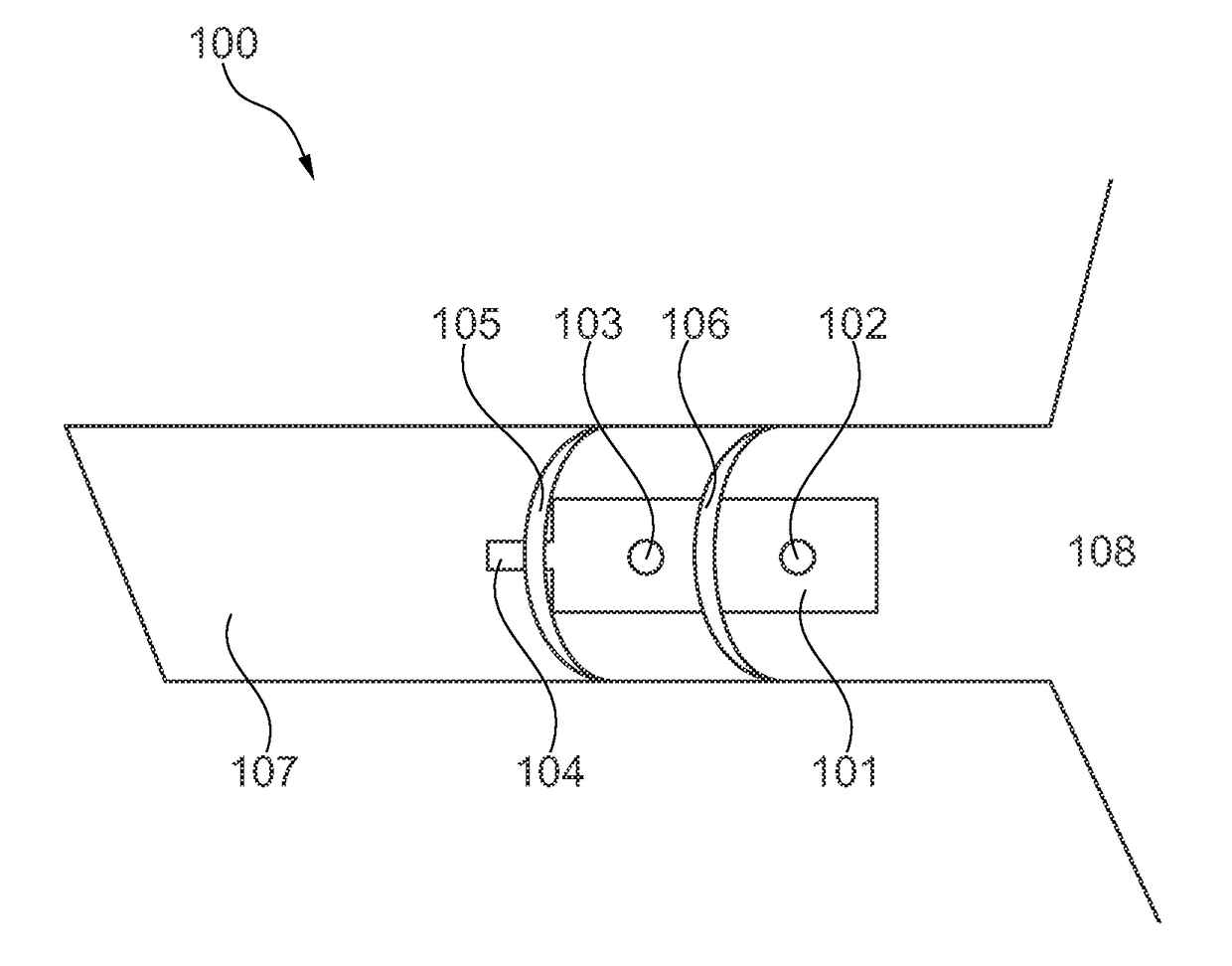
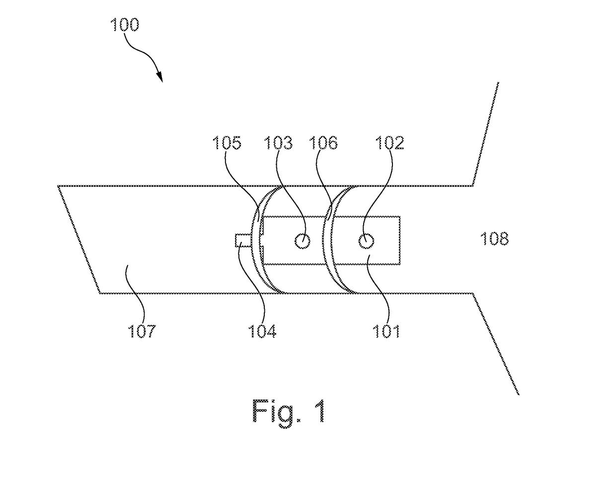
[0056]Referring now to FIG. 1 an embodiment 100 of the present invention is depicted. As seen the acoustical module 101 comprises two acoustical pressure pick-up points 102, 103 for receiving incoming sound from the outer ear 108. The acoustical module is positioned in the ear channel 107 with a sound generating receiver 104 facing the eardrum (not shown). A pair or dome shaped acoustical filters 105, 106 improve the wearing comfort of the acoustical module while being positioned in the ear channel 107. The dome 106 forms an acoustical filter between acoustical pressure pick-up point 102 and 103 so that acoustical sound arriving from the outer ear 108 is attenuated before arriving at pressure pick-up point 103. Thus, the acoustical sound signal reaching pressure pick-up point 103 is attenuated relative to the acoustical sound pressure reaching pressure pick-up point 102. By applying the above-mentioned signal processing algorithm the influence of self-generated acoustical signals as...

embodiment 300

[0061]FIG. 3 shows a simple embodiment 300 of the present invention. As seen the acoustical module 301 comprises two acoustical pressure pick-up points 302, 303 for receiving incoming sound from the outer ear 307. The acoustical module is positioned in the ear channel 306 with a sound generating receiver 304 facing the eardrum (not shown). A dome shaped acoustical filter 305 is positioned between acoustical pressure pick-up point 302 and 303 so that acoustical sound arriving from the outer ear 307 is attenuated before arriving at pressure pick-up point 303. Thus, the acoustical sound signal reaching pressure pick-up point 303 is attenuated relative to the acoustical sound pressure reaching pressure pick-up point 302.

embodiment 400

[0062]Referring now to FIG. 4 an embodiment 400 of the present invention is depicted. As seen the acoustical module 401 comprises two acoustical pressure pick-up points 402, 403 for receiving incoming sound from the outer ear 408. The acoustical module is positioned in the ear channel 407 with a sound generating receiver 404 facing the eardrum (not shown). A pair or dome shaped acoustical filters 405, 406 improve the wearing comfort of the acoustical module while being positioned in the ear channel 407. The dome 406 forms an acoustical filter between acoustical pressure pick-up point 402 and 403 so that acoustical sound arriving from the outer ear 408 is attenuated before arriving at pressure pick-up point 403. By applying the above-mentioned signal processing algorithm the influence of self-generated acoustical signals as well as self-generated vibration signals can be attenuated.

[0063]The dome 406 is attached to or integrated with the sleeve 409 which is dimensioned to match the o...


PUM


Abstract

An acoustical module including a receiver unit for generating audio sound, microphone units for receiving acoustical pressure signals, and acoustical pressure pick-up points. Each of the acoustical pressure pick-up points is acoustically connected to a microphone unit. The module further includes an acoustical filter for attenuating acoustical pressure signals from a first acoustical pressure pick-up point relative to a second acoustical pressure pick-up point. The invention further relates to a hearing device comprising an acoustical module.

Description

FIELD OF THE INVENTION[0001]The present invention relates to an acoustical module configured to separate sound pressure signals from external sources. In particular, the present invention relates to an acoustical module where the influence of self-generated signals is attenuated.BACKGROUND OF THE INVENTION[0002]Various arrangements involving two sound detectors have been suggested over the years.[0003]An example is U.S. Pat. No. 8,259,976 where an assembly comprising a sound emitter and at least two sound detectors fixed to each other is disclosed. Each detector has a sound receiving opening. The sound receiving openings of at least two of the detectors point in opposite directions. However, there is in U.S. Pat. No. 8,259,976 no disclosure of a feedback suppression algorithm for reducing the influence of self-generated signals, such as acoustic signals and vibration signals.[0004]It may be seen as an object of embodiments of the present invention to provide an acoustical module whe...

Claims


Application Information

Patent Timeline
Patent Type & Authority Applications(United States)
IPC IPC(8): H04R25/00H04R1/08
CPCH04R25/35H04R25/405H04R2225/43H04R2225/025H04R1/086H04R25/453H04R25/604H04R25/656
Inventor TIEFENAU, ANDREASVAN GILST, KOENDE RUIJTER, LAURENSSTOFFELS, NICOLAAS MARIA JOZEFGESKUS, MIKEVOSS, RASMUS
Owner SONION NEDERLAND
Why Eureka
Try Eureka