Thermoplastic wheel hub

a hub and thermoplastic technology, applied in the field of tires, can solve the problems of adding weight to the vehicle, and achieve the effects of reducing weight, minimizing sink marks, and providing dimensional stability

Active Publication Date: 2017-03-30
BASF AG
View PDF7 Cites 7 Cited by
  • Summary
  • Abstract
  • Description
  • Claims
  • Application Information

AI Technical Summary

Benefits of technology

[0008]One advantage of the present invention is that a thermoplastic wheel hub is provided for mounting a non-pneumatic tire thereon. Another advantage of the present invention is that the thermoplastic wheel hub meets load and structural requirements for braking, cornering, fatigue, impact, etc. Yet another advantage of the present invention is that the thermoplastic wheel hub incorporates compression limiters to help support loads in high stress areas. Still another advantage of the present invention is that the thermoplastic wheel hub uses structural ribs to distribute the loads throughout the wheel hub. A further advantage of the present invention is that the thermoplastic wheel hub has rib thickness and placement for both strength and appearance, minimizing sink marks. Yet a further advantage of the present invention is that the thermoplastic wheel hub has a uniform wall thickness to provide dimensional stability and weight reduction. Still a further advantage of the present invention is that the thermoplastic wheel hub reduces weight compared to conventional wheel hubs.
[0009]Other features and advantages of the present invention will be readily appreciated, as the same becomes better understood, after reading the subsequent description taken in conjunction with the accompanying drawings.

Problems solved by technology

In addition, these metal wheel hubs add significant weight to the wheel, resulting in additional weight for the vehicle.

Method used


Image

  • Thermoplastic wheel hub
  • Thermoplastic wheel hub
  • Thermoplastic wheel hub

Examples


Embodiment Construction

)

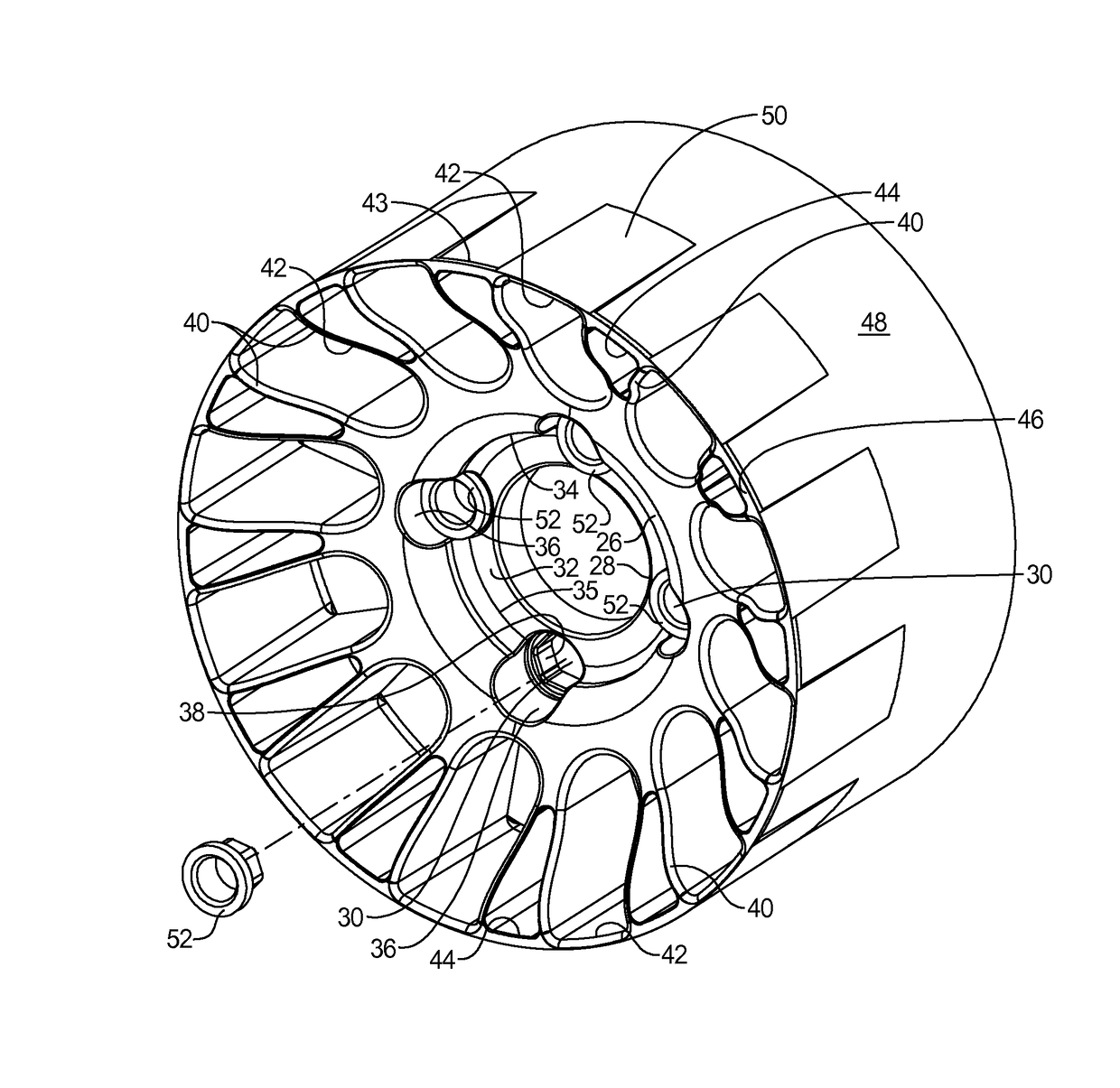
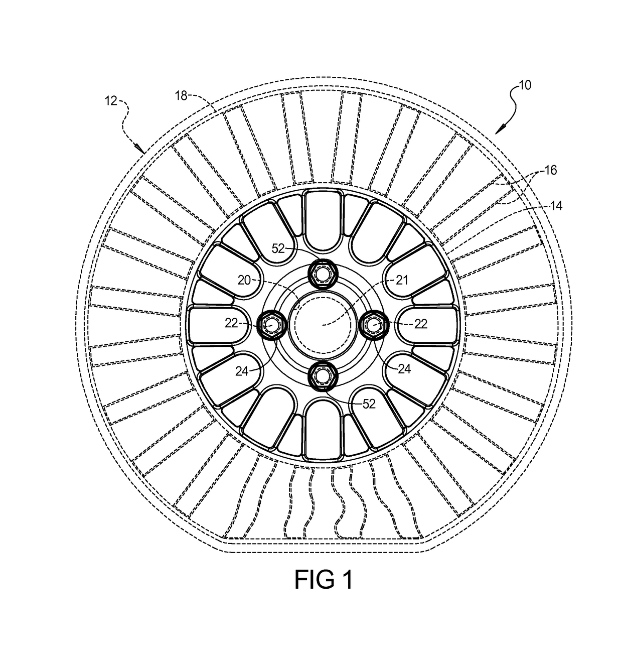
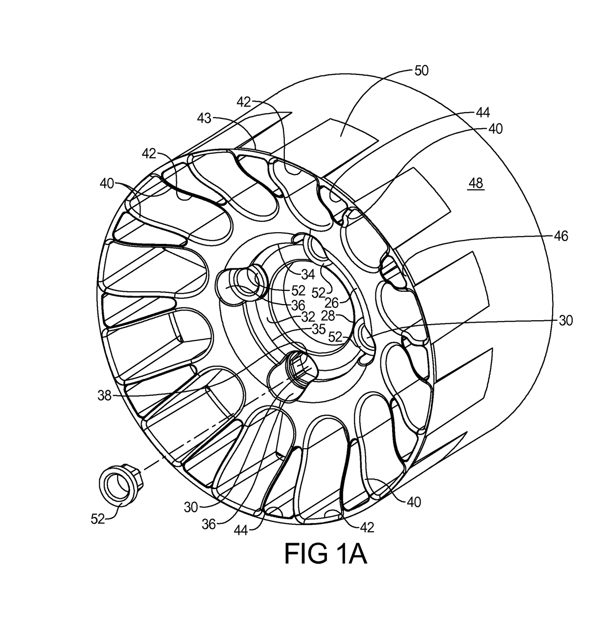
[0025]Referring to the figures, wherein like numerals indicate like parts throughout the several views, one embodiment of a thermoplastic wheel hub, according to the present invention, is shown generally at 10. The thermoplastic wheel hub 10 is configured to have a non-inflatable or non-pneumatic tire, generally indicated at 12, mounted thereon to form a wheel for a vehicle (not shown). As illustrated in FIG. 1, the non-pneumatic tire 12 includes an annular inner band 14, a plurality of spokes or web elements 16 arranged circumferentially about the inner band 14, and an annular outer band 18 disposed across the spokes or web elements 16, forming an outer edge of the tire 12. The outer band 18 includes a tread (not shown) for contact with a surface of a road. The non-pneumatic tire 12 supports its load solely through the structural properties of its tread, outer band 18, spokes or web elements 16, and inner band 14 without support from internal air pressure. The non-pneumatic tire 1...


PUM

PropertyMeasurementUnit
diameteraaaaaaaaaa
average diameteraaaaaaaaaa
surface roughnessaaaaaaaaaa

Abstract

A thermoplastic wheel hub (10) includes a center hub (26) for attachment to a wheel bearing (20) of a vehicle. The center hub (26) has a central shaft aperture (28) extending axially therethough and a plurality of lug apertures (30) spaced radially from and circumferentially about the central shaft aperture (28). The thermoplastic wheel hub (10) also includes a plurality of ribs (40) extending radially outwardly from the center hub (26). The thermoplastic wheel hub (10) further includes a cylindrical tire mount (46) connected to the ribs and extending axially in substantially a plane for mounting a non-pneumatic tire (12) thereon.

Description

BACKGROUND OF THE INVENTION[0001]1. Field of the Invention[0002]The present invention relates generally to tires and, more particularly, to a thermoplastic wheel hub for a non-pneumatic tire.[0003]2. Description of the Related Art[0004]It is known to provide a wheel for a vehicle. Typically, the wheel includes a wheel hub mounted to a wheel bearing and axle of the vehicle and an inflatable or pneumatic tire mounted to the wheel hub. Recently, some wheels have been provided with a non-pneumatic or non-inflatable tire mounted to the wheel hub. Non-pneumatic tires, such as the TWEEL® non-pneumatic tire, are not inflatable. Typically, the non-pneumatic tire has an inner interface band portion for engaging the outer surface of the wheel hub and a plurality of spokes or web elements surrounding the inner interface band portion. The non-pneumatic tire also has an outer band concentrically positioned outside the inner interface band portion and positioned at the outer end of the spokes or w...

Claims


Application Information

Patent Timeline
Patent Type & Authority Applications(United States)
IPC IPC(8): B60B5/02B60B1/06B60B9/26B60B27/06B60B21/10
CPCB60B5/02B60C2007/146B60B21/108B60B9/26B60B1/06B60B2360/32B60B2310/60B60B2360/36B60B2360/341B60B2360/3412B60B2360/3416B60B2360/322B60B2360/324B60B2310/204B60C7/24B60B27/065B60B21/10B60B2310/20B60C7/146
Inventor MCMASTER, WILLIAM J.SERNA, STEPHEN P.KONDAPALLI, PRASANNA
Owner BASF AG
Why Eureka
Try Eureka