Systems and apparatus for object detection

a technology of object detection and system, applied in the field of user input, can solve the problem that devices in these configurations cannot detect objects that can modulate capacitan

Active Publication Date: 2017-03-30
APPLE INC
View PDF18 Cites 124 Cited by
  • Summary
  • Abstract
  • Description
  • Claims
  • Application Information

AI Technical Summary

Benefits of technology

[0006]In some examples, a device can use acoustic touch sensors to determine the presence (and in some examples, characteristics of) objects touching the crown on a device. In some configurations, an acoustic touch sensor can use one or more acoustic waves emitted from an emitter (e.g., a transducer) into the crown or crown shaft. In these examples, the emitted acoustic wave can travel from an acoustic emitter at the near end of a crown shaft (i.e., the end distal to the crown), through the crown shaft, reflect off the far end (i.e., the end proximate to the crown) and return back to the near end, where it is received by an acoustic receiver. The received wave's strength and characteristics will depend on the material properties of the material (e.g., air, skin, fabric) at the crown. Thus, the received wave can be analyzed in order to determine the presence and, in some cases, the characteristics of any objects in contact with the crown. In addition, in some examples, the acoustic waves can be channeled through one or more acoustic channels in the crown shaft and/or crown. In some examples, the crown itself can be divided into acoustically isolated segments, each forming a portion of a touch sensor. Acoustic waves can be sent on each segment and analyzed to determine the presence and/or characteristics of an object touching a respective segment. In some examples, an acoustic touch sensor can use acoustic resonance to determine the presence and/or characteristics of an object touching the crown. In these configurations, a resonator can be operatively coupled to the crown or crown shaft, and the resonator can be configured to vibrate the crown or crown shaft. A sensor can detect the parameters of the vibration and detect the presence and/or characteristics of an object based on the parameters of the vibration (e.g., based on the amount of damping caused by the touching object.) In some configurations, the sensor can be coupled to the crown shaft or crown (e.g., when an accelerometer operates as a sensor) or not coupled to the crown shaft or crown (e.g., when a proximity sensor operates as a sensor). The acoustic touch sensors described herein can be useful to alert the device that the user is interacting (or is about to interact) with the crown or display, and in some cases, can cause the device to exit a rest state.
[0007]In some cases, the proximity sensor can be mounted such that the cover substrate (e.g., glass) refracts a field of view of the proximity detector. As a result, the proximity detector can detect the presence of an object to the side of the wearable device (i.e., adjacent to the device in a direction parallel to the plane of the display), even if the proximity sensor is not mounted normal to the side of the wearable device. For example, the proximity sensor can be mounted to an inner surface of the cover substrate, normal to a first angle with respect to the plane of the display. The field of view can refract through the cover substrate such that the field of view extending beyond the cover substrate is centered about a second angle, different than the first, with respect to the plane of the display. Consequently, the field of view of proximity sensor can include areas adjacent to the wearable device in a direction parallel to the plane of the display. This can be beneficial, for example, in detecting the presence of an object near a crown of the wearable device. In some examples, methods for detecting the presence of an object are described, including examples where the proximity sensor in the wearable device utilizes one or more light-pulsing schemes, including schemes where the light-pulse frequency can change during the operation of the proximity sensor. In some examples, the wearable device can perform one or more operations if the wearable device detects the presence of an object. In some examples, the wearable device can distinguish between the presence of an object which is touching the wearable device (e.g., touching the crown of the wearable device), and the presence of an object that is not touching the wearable device. In some configurations, the wearable device can wake from a power saving mode when a non-touching object is detected, and can perform a touch operation when a touching object is detected.
[0008]In some examples discussed herein, a proximity sensor can use an array of light detectors to detect the presence of objects. In some examples, the proximity sensor can determine the location of a centroid of light detected by the array of light detectors. Due to parallax in the imaging path of the array of light detectors, the position of the centroid detected by the array of light detectors can change as a function of the distance of the object to the proximity sensor. In some examples, the array of light detectors can be one or two-dimensional. In addition, in some examples, the size and/or shape of the light detected by the array of light detectors can be used to determine the distance and/or characteristics of an object. In some examples, the wearable device can perform one or more operations if the wearable device detects the presence of an object.
[0009]In some examples discussed herein, a proximity sensor can use multiple channels to detect the presence of objects. In some examples, the proximity sensor can have two or more light emitters...

Problems solved by technology

However, in some cases, devices in these configurati...

Method used


Image

  • Systems and apparatus for object detection
  • Systems and apparatus for object detection
  • Systems and apparatus for object detection

Examples


Embodiment Construction

[0093]In the following description of the disclosure and examples, reference is made to the accompanying drawings in which it is shown by way of illustration specific examples that can be practiced. It is to be understood that other examples can be practiced and structural changes can be made without departing from the scope of the disclosure.

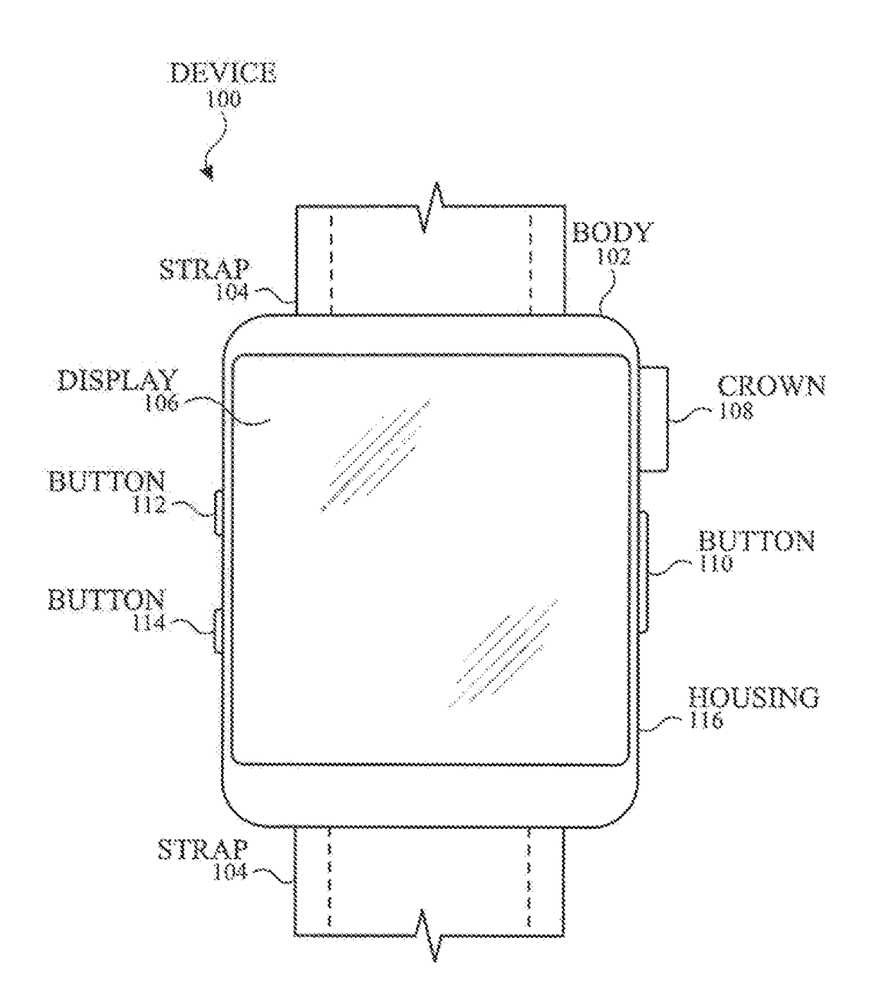
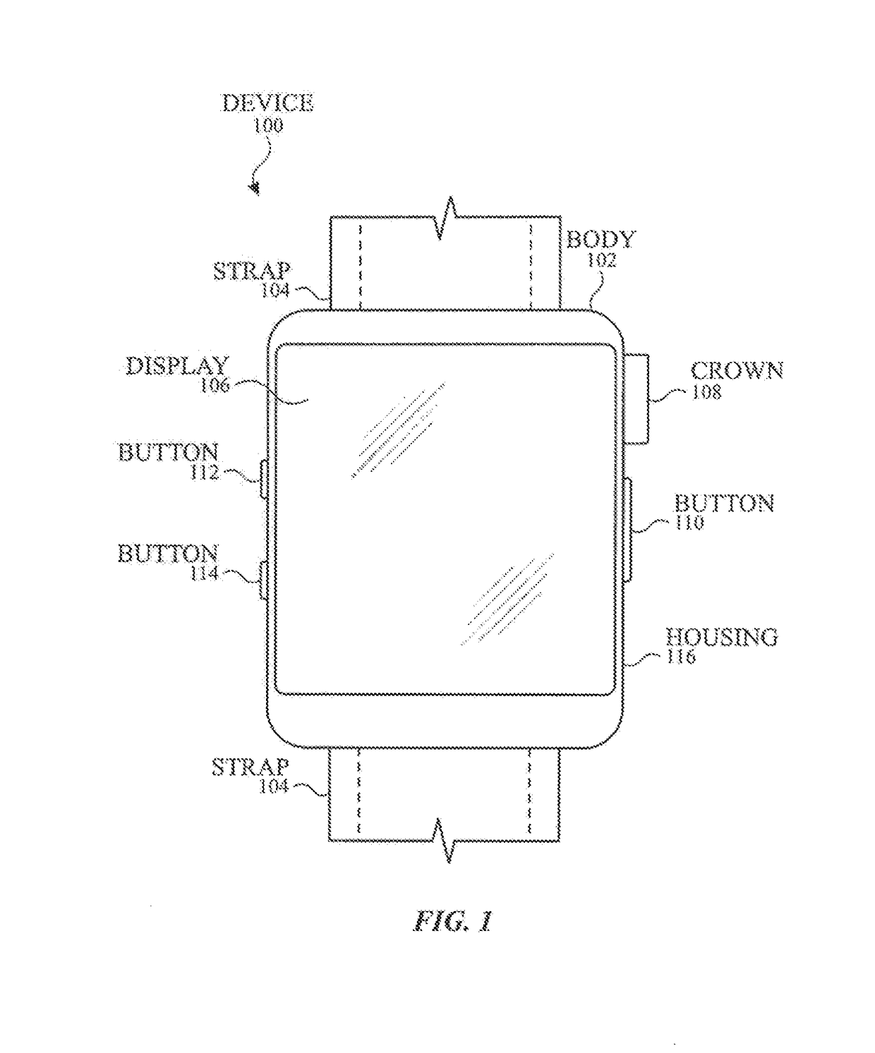
[0094]FIG. 1 illustrates exemplary personal electronic device 100 including a crown according to examples of the disclosure. In the illustrated example, device 100 is a watch that generally includes housing 102 and strap 104 for affixing device 100 to the housing of a user. That is, device 100 is a wearable device. Housing 102 can be designed to couple to straps 104. Device 100 can have touch-sensitive display screen 106 (hereafter display) and crown 108. Device 100 can also have buttons 112 and 114. Though device 100 is illustrated as a watch, it is understood that the examples of the disclosure can be implemented in devices other than watches...


PUM


Abstract

An electronic device is disclosed. In some examples, the electronic device comprises a rotatable mechanical input mechanism. In some examples, the electronic device comprises sense electrode positioned proximate to the mechanical input mechanism. In some examples, the electronic device comprises a capacitive sense circuit comprising drive circuity operatively coupled to the mechanical input mechanism and configured for driving a drive signal onto the mechanical input mechanism. In some examples, the electronic device comprises a capacitive sense circuit comprising sense circuitry operatively coupled to the sense electrode and configured to measure an amount of coupling between the rotatable mechanical input mechanism and the sense electrode. In some examples, the electronic device comprises a housing, wherein the sense electrode is included in a gasket for connecting a display to the housing.

Description

CROSS-REFERENCES TO RELATED APPLICATIONS[0001]This application claims the benefit under 35 U.S.C. §119(e) of U.S. Provisional Patent Application No. 62 / 235,465, filed Sep. 30, 2015, of U.S. Provisional Patent Application No. 62 / 235,254, filed Sep. 30, 2015, of U.S. Provisional Patent Application No. 62 / 235,473, filed Sep. 30, 2015, of U.S. Provisional Patent Application No. 62 / 235,426, filed Sep. 30, 2015, of U.S. Provisional Patent Application No. 62 / 297,780, filed Feb. 19, 2016, of U.S. Provisional Patent Application No. 62 / 304,129, filed Mar. 4, 2016, and of U.S. Provisional Patent Application No. 62 / 304,135, filed Mar. 4, 2016, the contents of which are incorporated by reference herein in their entirety for all purposes.FIELD OF THE DISCLOSURE[0002]This relates generally to user inputs, such as mechanical inputs, and more particularly, to providing touch and proximity sensing for such inputs.BACKGROUND OF THE DISCLOSURE[0003]Many types of input devices are presently available fo...

Claims


Application Information

Patent Timeline
IPC IPC(8): G06F3/038G06F3/041G06F3/03G06F1/16G06F3/044G06F3/043G06F3/0354G06F3/0362
CPCG06F3/038G06F3/03547G06F3/0414G06F3/0362G06F2203/04108G06F3/044G06F3/0433G06F3/0325G06F1/163G04C3/001G04C3/005G04C3/007G04G21/08G06F3/0304G06F2203/04105H03K17/962H03K2217/96003
Inventor KUBOYAMA, YUTABOKMA, LOUIS W.DE JONG, ERIKDODSON, CHRISTOPHER M.ELY, COLIN M.HOLENARSIPUR, PRASHANTHHUANG, MENGSHUISIKMAN, SERHAN O.LAND, BRIAN R.RAI, ANANTWANG, ALBERTWITTENBERG, MICHAEL B.
Owner APPLE INC
Why Eureka
Try Eureka