
Ion implantation apparatus

Active Publication Date: 2017-03-30
SUMITOMO HEAVY IND ION TECH
View PDF4 Cites 3 Cited by
  • Summary
  • Abstract
  • Description
  • Claims
  • Application Information

AI Technical Summary

Benefits of technology

The present invention aims to address difficulties in ion implantation processing by providing an apparatus that combines high productivity with accuracy in wafer in-plane non-uniform implantation.

Problems solved by technology

If the beam setup process must be performed each time of changing the wafer rotation angle, this will significantly lower productivity of the ion implantation processing.

Method used


Image

  • Ion implantation apparatus
  • Ion implantation apparatus
  • Ion implantation apparatus

Examples


Embodiment Construction

[0030]The invention will now be described by reference to the preferred embodiments. This does not intend to limit the scope of the present invention, but to exemplify the invention.

[0031]Hereinafter, embodiments of the present invention will be described in detail with reference to the drawings. In description of the drawings, the same reference numeral is assigned to the same element, and duplicate description thereof will not be presented as is appropriate. The configuration described below is merely an example but does not limit the scope of the present invention.

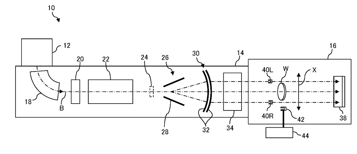
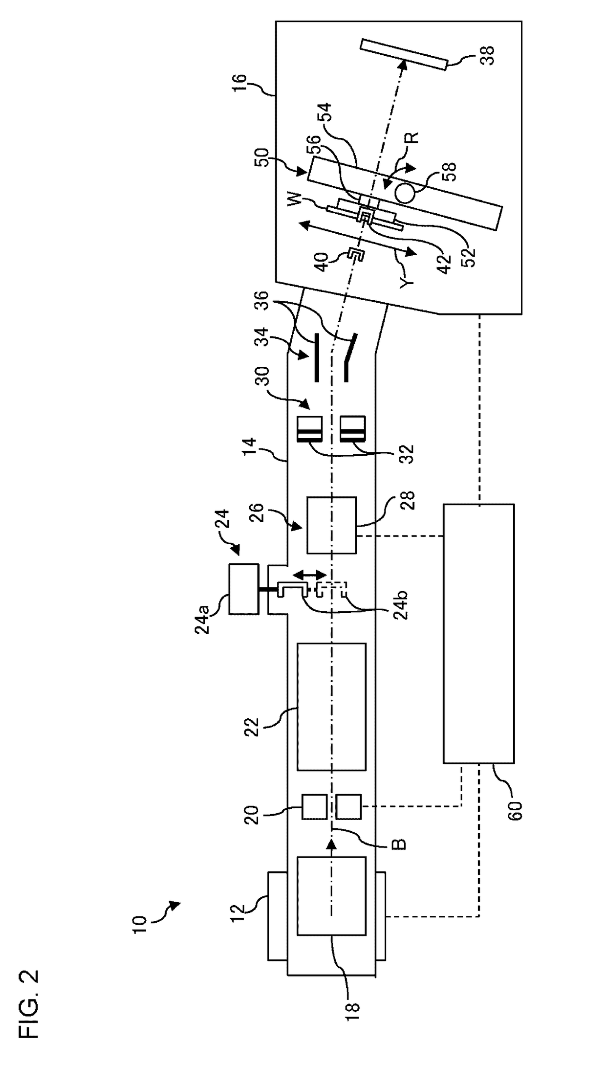
[0032]Before describing the embodiments, an overview of the present invention will be described. An ion implantation apparatus according to an embodiment is an ion implantation apparatus configured to perform a plurality of ion implantation processes having different implantation conditions to a same wafer successively. This ion implantation apparatus includes a beam scanner that causes an ion beam to scan in a reciproc...


PUM


Abstract

An ion implantation apparatus performs a plurality of ion implantation processes having different implantation conditions to a same wafer successively. The plurality of ion implantation processes are: (a) provided so that twist angles of the wafer differ from each other; (b) configured so that an ion beam is irradiated to a wafer surface to be processed that moves in a reciprocating movement direction; and (c) provided so that a target value of a beam current density distribution of the ion beam is variable in accordance with a position of the wafer in the reciprocating movement direction. Before performing the plurality of ion implantation processes to the same wafer successively, a control device executes a setup process in which a plurality of scanning parameters corresponding to the respective implantation conditions of the plurality of ion implantation processes are determined collectively.

Description

RELATED APPLICATION[0001]Priority is claimed to Japanese Patent Application No. 2015-193965, filed on Sep. 30, 2015, the entire content of which is incorporated herein by reference.BACKGROUND OF THE INVENTION[0002]1. Field of the Invention[0003]The present invention relates to an ion implantation apparatus configured to perform a plurality of ion implantation processes to a same wafer successively.[0004]2. Description of the Related Art[0005]In a semiconductor production process, a process of implanting ions into a semiconductor wafer (hereinafter, it may be referred to as an “ion implantation process”) is generally performed for the purpose of changing the conductivity and / or the crystalline structure of the semiconductor and the like. An apparatus that is used in the ion implantation process is called an ion implantation apparatus and has a function of forming an ion beam by generating ions using an ion source and accelerating the generated ions and a function of transporting the ...

Claims


Application Information

Patent Timeline
IPC IPC(8): H01J37/317H01L21/265
CPCH01L21/265H01J37/3171H01J37/20H01J37/3023H01L21/67011H01L21/68764H01J2237/31701H01J2237/20221H01J2237/20214H01J2237/20207H01L21/26586H01J37/304H01J2237/31703H01J2237/30483H01J2237/20228
Inventor NINOMIYA, SHIROOKAMOTO, YASUHARUOCHI, AKIHIROUENO, YUSUKE
Owner SUMITOMO HEAVY IND ION TECH
Learn More