Electronic card connector
- Summary
- Abstract
- Description
- Claims
- Application Information
AI Technical Summary
Benefits of technology
Problems solved by technology
Method used
Image
Examples
Embodiment Construction
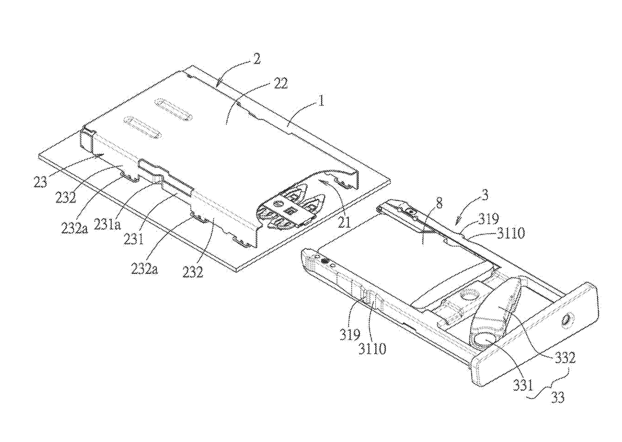
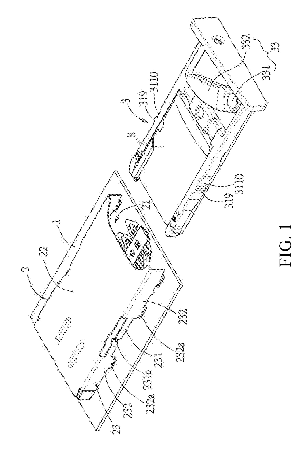
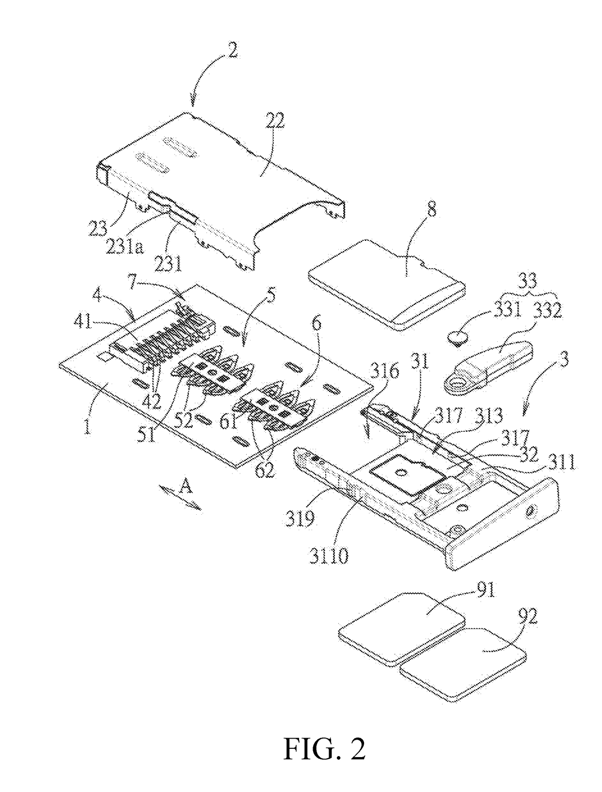
[0032]Referring to FIG. 1 through FIG. 4, an electronic card connector of an embodiment of the present disclosure is provided on a circuit board 1, and comprises a metal shell 2, a tray 3, a first terminal block 4, a second terminal block 5, a third terminal block 6 and a detection switch 7.
[0033]The metal shell 2 is provided on the circuit board 1, and the metal shell 2 cooperates with the circuit board 1 to define a slot 21. The tray 3 is used to receive a SD card 8, a first SIM card 91 and a second SIM card 92, and is inserted into and ejected from the slot 21 along an inserting-ejecting direction A. The tray 3 comprises an insulative body 31 and a shielding unit 32. The insulative body 31 has a top surface 311, a bottom surface 312 opposite to the top surface 311, a first receiving groove 313, a second receiving groove 314, a third receiving groove 315 and an opening region 316. The first receiving groove 313 is formed on the top surface 311 so as to receive the SD card 8, the s...
PUM
 Abstract
Description
Claims
Application Information
 - R&D
- Intellectual Property
- Life Sciences
- Materials
- Tech Scout
- Unparalleled Data Quality
- Higher Quality Content
- 60% Fewer Hallucinations
Browse by: Latest US Patents, China's latest patents, Technical Efficacy Thesaurus, Application Domain, Technology Topic, Popular Technical Reports.
© 2025 PatSnap. All rights reserved.Legal|Privacy policy|Modern Slavery Act Transparency Statement|Sitemap|About US| Contact US: help@patsnap.com


