Lens driving device, and camera module and optical device comprising same

Active Publication Date: 2021-06-17
LG INNOTEK CO LTD
View PDF0 Cites 1 Cited by
  • Summary
  • Abstract
  • Description
  • Claims
  • Application Information

AI Technical Summary

Benefits of technology

[0017]According to embodiments, it is possible to reduce magnetic field interference, to reduce size, to reduce current consumption, and to improve sensitivity in OIS driving.
[0018]In addition, according to embodiments, it is possible to reduce

Problems solved by technology

It is difficult to apply technology of a voice coil motor (VCM) used in existing general camera modules to

Method used


Image

  • Lens driving device, and camera module and optical device comprising same
  • Lens driving device, and camera module and optical device comprising same
  • Lens driving device, and camera module and optical device comprising same

Examples


Example

BEST MODE

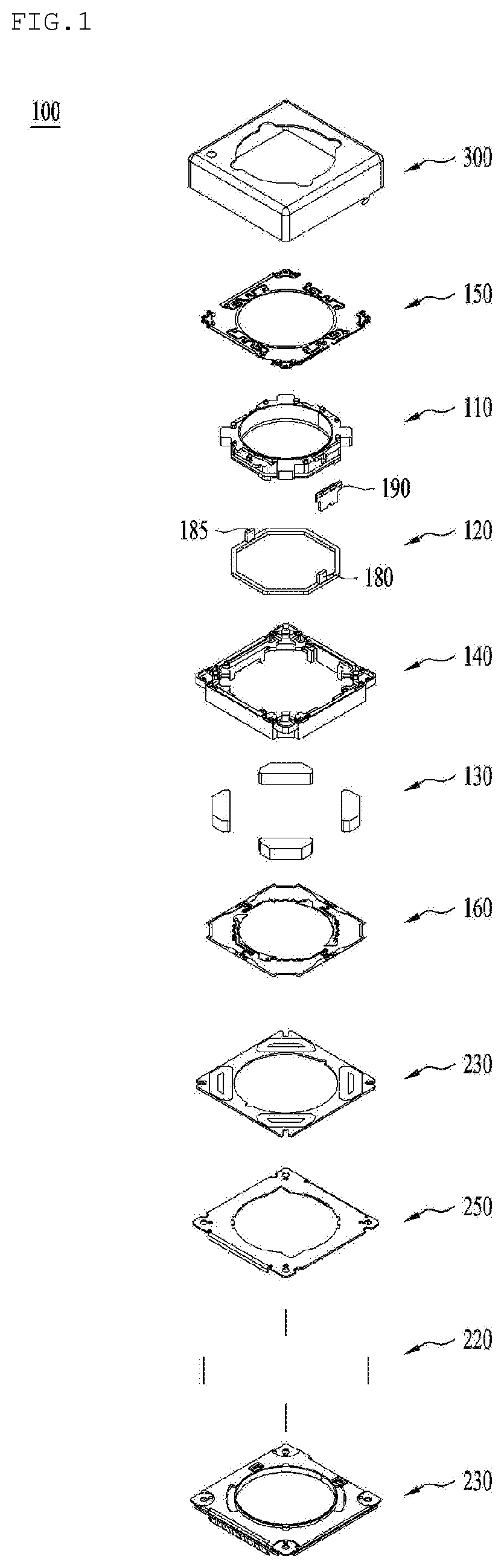
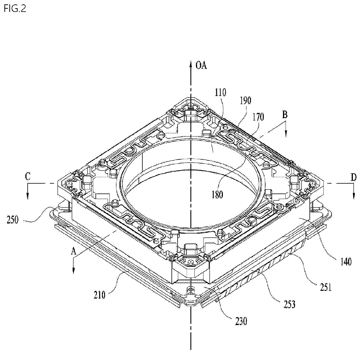
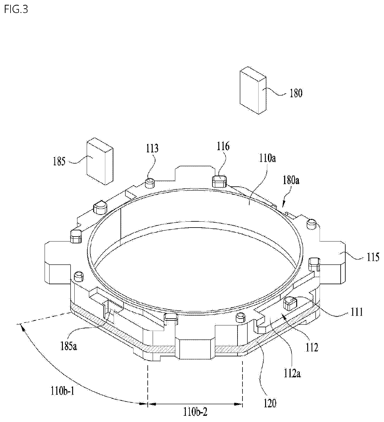
[0078]Reference will now be made in detail to embodiments, examples of which are illustrated in the accompanying drawings. In the following description of the embodiments, it will be understood that, when a layer (film), region, pattern, or structure is referred to as being “on” or “under” another layer (film), region, pattern, or structure, it can be “directly” on or under the other layer (film), region, pattern, or structure or can be “indirectly” formed such that an intervening element is also present. In addition, terms such as “on” or “under” should be understood on the basis of the drawings.

[0079]In the drawings, the sizes of respective elements are exaggerated, omitted, or schematically illustrated for convenience and clarity of description. Further, the sizes of the respective elements do not denote the actual sizes thereof. In addition, wherever possible, the same reference numbers will be used throughout the drawings to refer to the same or like parts.

[0080]Herein...


PUM


Abstract

An embodiment comprises: a housing; a bobbin arranged inside the housing; a first coil arranged on the bobbin; first magnets arranged on first to fourth corner portions of the housing, respectively; a first circuit board which is arranged on a first side portion of the housing, and which comprises a first terminal, a second terminal, a third terminal, and a fourth terminal; a first position sensor arranged on the first circuit board and electrically connected to the first to fourth terminals; a first upper elastic unit arranged on the first corner portion of the housing; a second upper elastic unit arranged on the second corner portion of the housing; a third upper elastic unit arranged on the third corner portion of the housing; and a fourth upper elastic unit arranged on the fourth corner portion of the housing. One end of the first upper elastic unit extends from the first corner portion to the first side portion of the housing and is coupled to the first terminal. One end of the second upper elastic unit extends from the second corner portion to the first side portion of the housing and is coupled to the second terminal. One end of the third upper elastic unit extends from the third corner portion to the first side portion of the housing and is coupled to the third terminal. One end of the fourth upper elastic unit extends from the fourth corner portion to the first side portion of the housing and is coupled to the fourth terminal.

Description

CROSS REFERENCE TO RELATED APPLICATIONS[0001]This application is the National Phase of PCT International Application No. PCT / KR2018 / 008603, filed on Jul. 30, 2018, which claims priority under 35 U.S.C. 119(a) to Patent Application No. 10-2017-0098882, filed in the Republic of Korea on Aug. 4, 2017, Patent Application No. 10-2017-0108542, filed in the Republic of Korea on Aug. 28, 2017, and Patent Application No. 10-2018-0073242, filed in the Republic of Korea on Jun. 26, 2018, all of which are hereby expressly incorporated by reference into the present application.TECHNICAL FIELD[0002]Embodiments relate to a lens moving apparatus, and a camera module and optical instrument including the same.BACKGROUND ART[0003]It is difficult to apply technology of a voice coil motor (VCM) used in existing general camera modules to a subminiature, low-power camera module, and therefore research related thereto has been actively conducted.[0004]Demand for and production of electronic products, such ...

Claims


Application Information

Patent Timeline
IPC IPC(8): G02B7/09G03B5/02G03B17/12G02B7/02
CPCG02B7/09G02B7/021G03B17/12G03B5/02G03B5/00G03B3/10G03B2205/0069G03B2205/0007G03B30/00
Inventor PARK, SANG OKLEE, SUNG GUKMIN, SANG JUN
Owner LG INNOTEK CO LTD
Why Eureka
Try Eureka