Electronic card connector

Active Publication Date: 2017-03-30
MOLEX INC
View PDF10 Cites 6 Cited by
  • Summary
  • Abstract
  • Description
  • Claims
  • Application Information

AI Technical Summary

Benefits of technology

[0013]The present disclosure at least has the following beneficial effects: when the tray is improperly inserted (that is the tray is turned upside down and inserted), because the side stopping surface of the limiting arm abuts against the interference oblique surface of the tray, the force applied by the interference oblique surface may be dispersed toward different directions, thereby reducing the risk of scrapping the tray and assuring the fool-proof function. Similarly, because the front stopp

Problems solved by technology

However, when the tray is improperly inserted, the fool-proof bended arm blocks the try by use of an edge of the fool-proof bended arm, but the edge is thin and small, and is as s

Method used


Image

  • Electronic card connector
  • Electronic card connector
  • Electronic card connector

Examples


Example

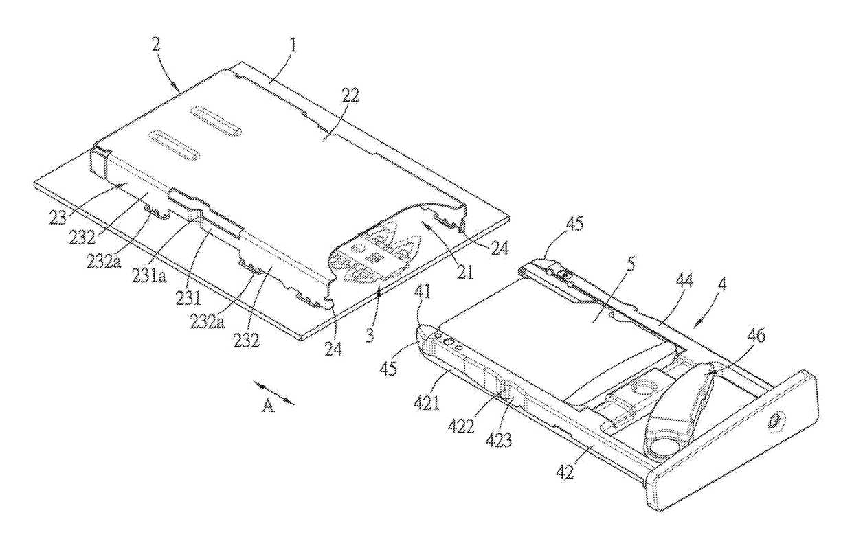
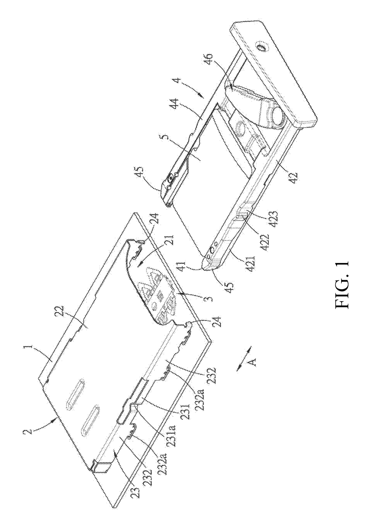
[0029]Referring to FIG. 1 through FIG. 5, an electronic card connector of a first embodiment of the present disclosure is provided on a circuit board 1, and comprises a metal shell 2, three terminal blocks 3 and a tray 4.

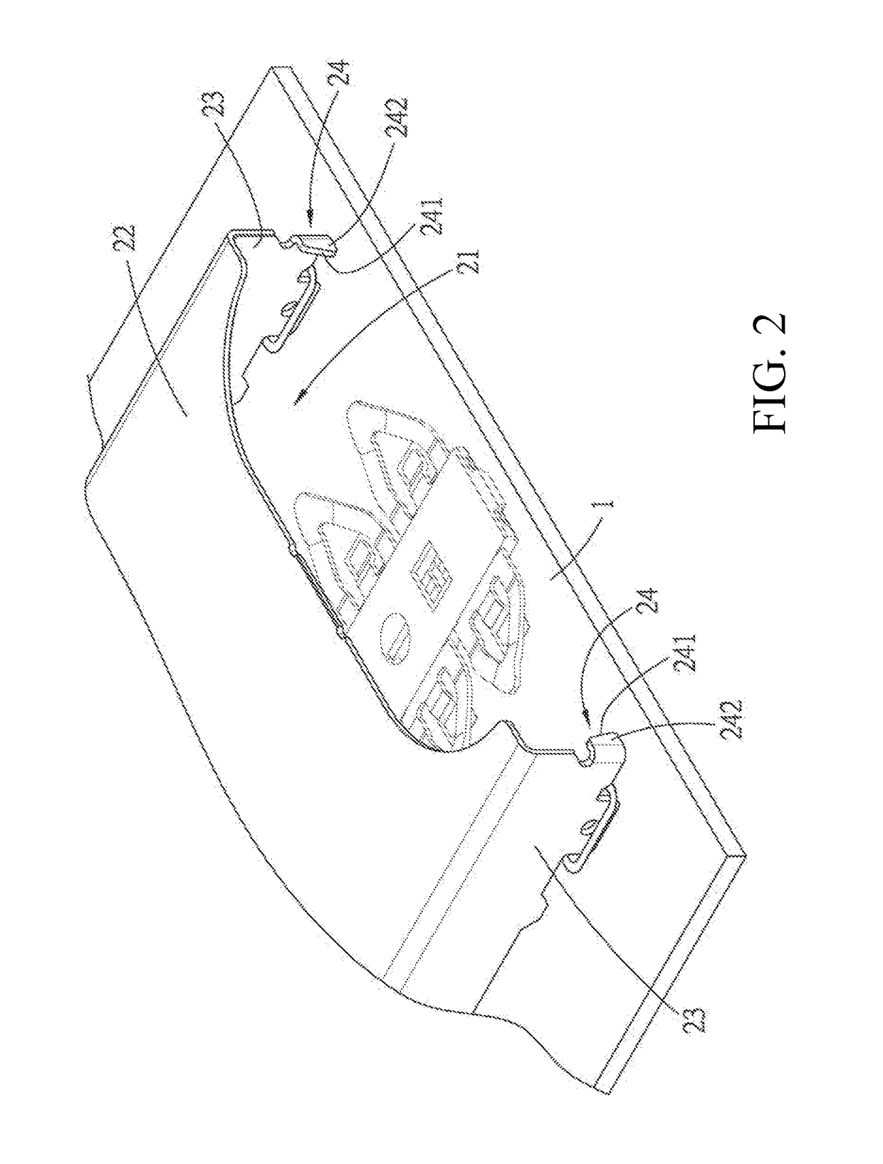
[0030]The metal shell 2 is provided on the circuit board 1 and the metal shell 2 cooperates with the circuit board 1 to define a slot 21. The metal shell 2 has a top plate 22 which is spaced apart from and faces the circuit board 1, two side plates 23 which are respectively connected to two sides of the top plate 22 and face each other, and two limiting arms 24 which are respectively bent from two end edges of the two side plates 23 adjacent to an entrance of the slot 21 and perpendicular to the top plate 22 and extend toward each other, each limiting arm 24 is spaced apart from the top plate 22 and has a side stopping surface 241 toward the other limiting arm 24 and a front stopping surface 242 toward the outside of the slot 21. In the embodiment, the two limiting ...

Example

[0035]Referring to FIG. 13 and FIG. 14, an electronic card connector of a second embodiment of the present disclosure is substantially the same as that of the first embodiment, however, in the second embodiment, a width between the two sides of the insertion end 41 of the tray 4 is wider than that of the first embodiment and the interference oblique surface 45 is eliminated, when the tray 4 is improperly inserted (that is the tray 4 is turned upside down and inserted), two parts of the insertion end 41 respectively adjacent to the two sides of the insertion end 41 of the tray 4 respectively abut against the two front stopping surfaces 242 of the two limiting arms 24, so that the tray 4 cannot enter into the slot 21. In the embodiment, two end surfaces respectively adjacent to the two sides of the tray 4 respectively abut against the two front stopping surfaces 242 of the two limiting arms 24. The tray 4 is blocked by the two front stopping surfaces 242 of the two limiting arms 24, t...


PUM


Abstract

An electronic card connector includes a metal shell, a terminal block and a tray. The metal shell is provided on a circuit board and cooperates with the circuit board to define a slot having an entrance. The tray has an insertion end which first enters the slot of the metal shell and two receiving portions which are respectively parallel to two sides of the inserting-ejecting direction and respectively correspond to two limiting arms of the metal shell. The tray further has two interference oblique surfaces adjacent to the insertion end, when the tray is improperly inserted under a state that the tray is turned upside down, the two interference oblique surfaces respectively abut against the two limiting arms, therefore the tray cannot enter into the slot.

Description

RELATED APPLICATIONS[0001]This application claims priority to Chinese Application No. 201520771337.2, filed Sep. 30, 2015, which is incorporated herein by reference in its entirety.TECHNICAL FIELD[0002]The present disclosure relates to an electronic card connector, and more specifically relates to an electronic card connector comprising a tray.BACKGROUND ART[0003]Generally, an electronic card connector typically comprises a tray for carrying an electronic card with a small volume, such as a SIM card, or carrying a plurality of electronic cards at the same time, so as to facilitate use and operation of insertion and ejection of the electronic card(s).[0004]In order to prevent an operator from improperly inserting the electronic card, there is a fool-proof (i.e. prevent improper insertion) design on the electronic card connector, for example Chinese patent issuance publication No. CN204011822U discloses a card connector comprising a metal shell and a tray for carrying an electronic ca...

Claims


Application Information

Patent Timeline
IPC IPC(8): H01R13/26H01R13/635H01R13/645
CPCH01R13/26H01R13/635H01R13/6456G06K13/00
Inventor WANG, HONG-LIANGZENG, SHANG-XIULIM, KIAN HENG
Owner MOLEX INC
Why Eureka
Try Eureka