Mobile Communications Devices

a mobile communication and device technology, applied in the direction of reradiation, wireless communication services, instruments, etc., can solve the problems of multipath reflected, signal reflection, attenuation or blockage,

Inactive Publication Date: 2017-03-30
NABLE IT
View PDF6 Cites 5 Cited by
  • Summary
  • Abstract
  • Description
  • Claims
  • Application Information

AI Technical Summary

Benefits of technology

The present invention provides an apparatus that can communicate with wireless devices using a shrouded antenna arrangement that produces a pre-determined detection zone. This allows for the identification of wireless devices and tracking of their movement. The apparatus includes an RFAM shroud with an absorption profile that acts to form the detection zone. The technical effects of this invention are improved wireless communication and location tracking. Additionally, a system comprising the apparatus and a processor to identify the wireless device is also provided.

Problems solved by technology

While triangulation, and indeed trilateration and other similar methods, as such, are well-known location techniques, they have limitations, for example, when the transmitters and / or the receivers are located in built-up or generally ‘obstructed’ environments, which may lead to signals being reflected, attenuated or blocked.
Such obstructions can lead to unpredictable signal reflections (for example, causing multipath reflected signals) and / or attenuation of signals.
Reflected signals in particular can lead to inaccurate location determinations, as the distance and time-of-flight from transmitter to receiver of a reflected signal is typically longer than that of a signal that is transmitted directly in free space (that is, without reflection) between a transmitter and a receiver.
Shopping centres are perceived to be one example of a built-up and generally obstructed environment, in which the aforementioned location techniques may not always provide a reliable way to track accurately the location and / or movement of a mobile device (and the respective user).

Method used


Image

  • Mobile Communications Devices
  • Mobile Communications Devices
  • Mobile Communications Devices

Examples


Embodiment Construction

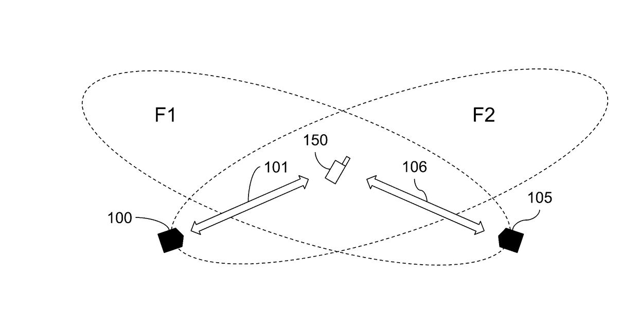
[0022]With reference to FIG. 1 and by way of further background, a plan view of a scene depicts first and second antennas 100 and 105, for example associated with respective wireless access points, which are shown to have relatively directional radiated fields, respectively, F1 and F2, and emit respective signals 101 and 106 (which are, for simplicity, depicted as arrows), including in directions towards a person carrying a wireless mobile device 150 (just the mobile device is shown for reasons of simplicity only). The mobile device 150 is within the range of the radiated fields, F1 and F2, of each antenna and so is able to receive signals. There are no obstructions between the antennas 100, 105 and the mobile device 150 and so communications can be direct, free space and line-of-sight. In this situation, the use of known techniques such as triangulation may be used to determine relatively accurately the location of the mobile device 150 relative to the known locations of the access...


PUM


Abstract

An apparatus for communicating with wireless devices is described. The apparatus in one form includes a shrouded antenna arrangement (700) which is arranged to produce a radiated field forming a pre-determined detection zone having a boundary, spaced apart from the arrangement. Outside of the boundary the energy of the radiated field is below a pre-determined cut-off threshold. The shrouded antenna arrangement (700) in one form comprises an antenna (705) within an RFAM shroud (710). The RFAM shroud (710) may then have an absorption profile that varies around the antenna to form the detection zone.

Description

TECHNICAL FIELD[0001]The present invention relates to locating and communicating with mobile communications devices.BACKGROUND[0002]It is known to be possible to locate wireless mobile communications devices (or simply ‘wireless devices’) by receiving signals emanating from such devices. When a signal is received, it may contain data identifying the device that transmitted the signal, and the broad location of the device may then be determined to be within a generally defined geographic area. Wireless devices may be mobile telephones, tablets or any other kind of mobile, portable or, indeed, movable device that is capable of communicating, for example, using any one or more known, standard communications protocols, such as 2G, 3G, LTE, NFC, Bluetooth, Wi-Fi, WiMAX, or any other known or future, for example, cellular, point-to-point or peer-to-peer communications protocol.[0003]WO2006 / 010774 describes a way of monitoring the movement of people carrying mobile devices within a specifi...

Claims


Application Information

Patent Timeline
IPC IPC(8): H04W4/02H04W64/00H04W4/04H04W4/021H04W4/029
CPCH04W4/021H04W64/006H04W4/043H04W4/023G01S1/68H01Q17/001G01S13/765H01Q1/2216H04W4/029
Inventor WARREN, PETERPALMER, JOHNWARREN, DEAN
Owner NABLE IT
Why Eureka
Try Eureka