
Computer system

a computer system and computer technology, applied in computing, input/output to record carriers, instruments, etc., can solve the problems of difficult to provide the high i/o performance of flash memory devices, and the inefficiency of conventional scsi (small computer system interfaces) executed in a server by programs

Inactive Publication Date: 2017-04-13
HITACHI LTD
View PDF8 Cites 25 Cited by
  • Summary
  • Abstract
  • Description
  • Claims
  • Application Information

AI Technical Summary

Benefits of technology

The patent text discusses the challenges of implementing high-performance input / output (I / O) in computer systems and the need for a solution. It also mentions the lack of specific information on how to use the NVMe standard for non-volatile memory (NVM) in different usage models, such as solid state drives, main memory, cache memory, etc. The text highlights the difficulty of providing virtualization of a namespace in NVMe. The technical effects of the patent text are the lack of clarity on how to implement the NS sharing concept and the challenges in providing a computer system with efficient and high-speed I / O.

Problems solved by technology

However, in connection with provision of the performance of the flash memory device, conventional SCSI (Small Computer System Interfaces) involves inefficient processing executed in a server by programs such as an OS (Operating System) and device drivers.
Thus, providing the high I / O performance of the flash memory device is not easy.

Method used


Image

  • Computer system
  • Computer system
  • Computer system

Examples


Embodiment Construction

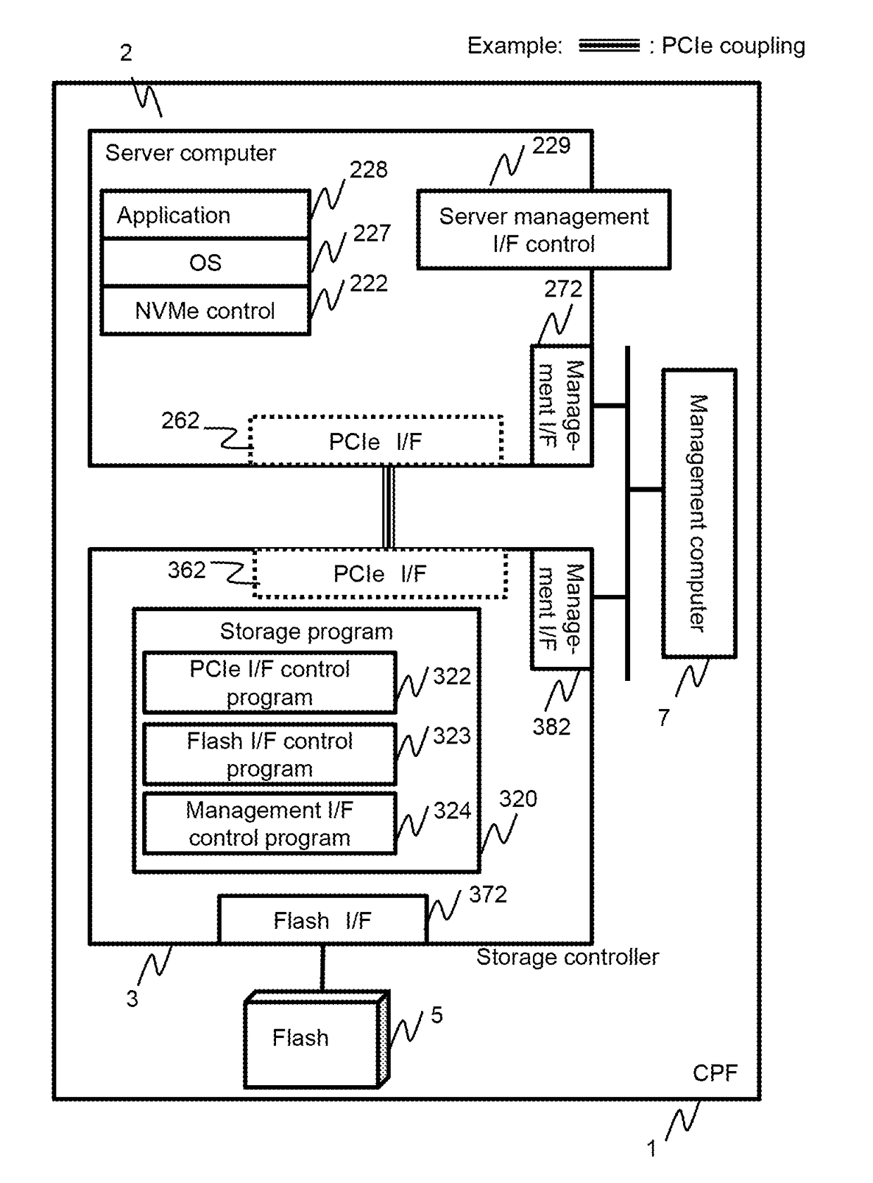
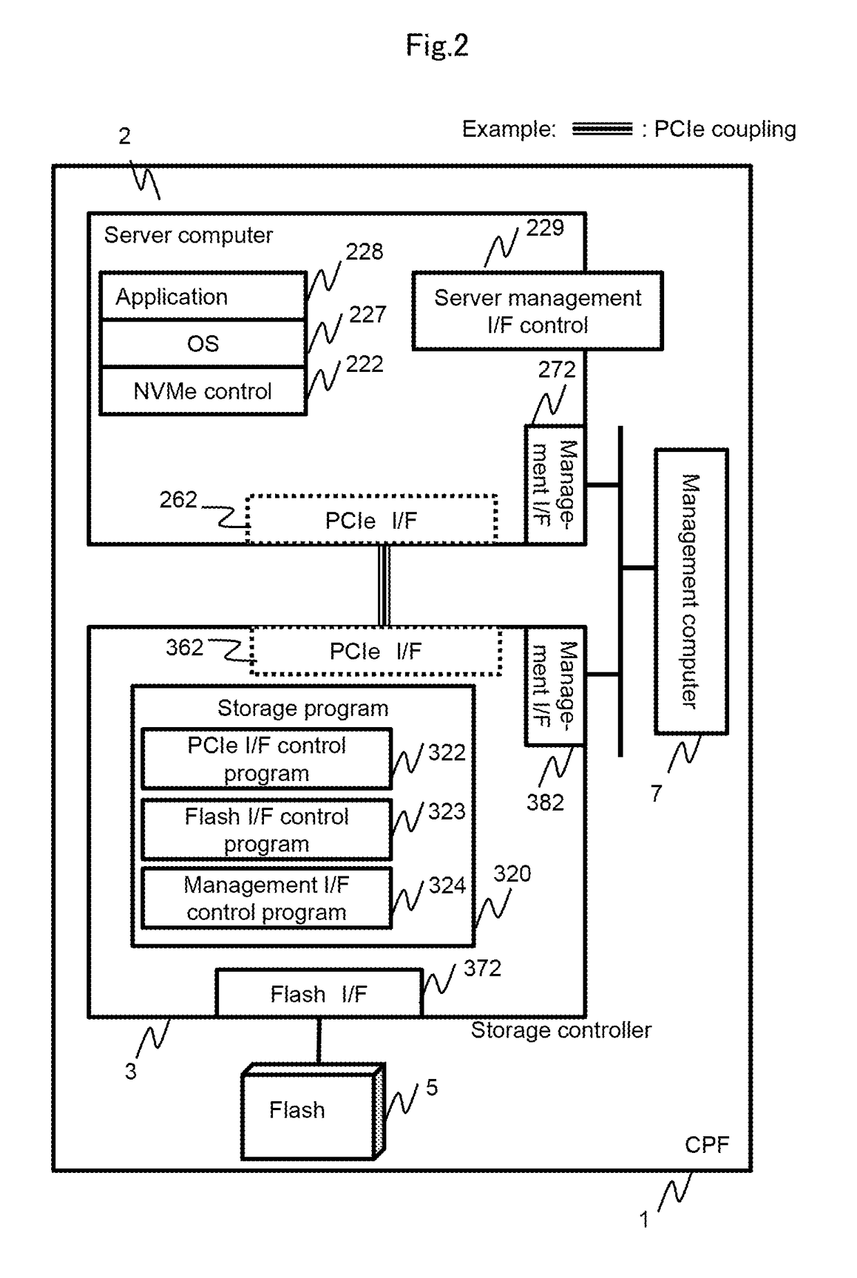
[0064]An embodiment will be described below with reference to the drawings. However, the present embodiment is only an example of implementation of the invention and is not intended to limit the technical scope of the invention. Furthermore, components common to the drawings are denoted by the same reference numerals.

[0065]Information in the present embodiment will be described using an expression “table”. However, the information need not necessarily be expressed in a data structure based on a table. For example, the information may be expressed in a data structure such as a “list”, a “DB (Database)”, or a “queue” or using any other structure. Thus, to indicate independence of the data structure, the “table”, the “list”, the “DB”, the “queue”, and the like may be simply referred to as “information”. Furthermore, when the contents of each type of information are described, expressions “identity”, “identifier”, “name”, and “ID” may be used and are interchangeable.

[0066]The subject in...


PUM


Abstract

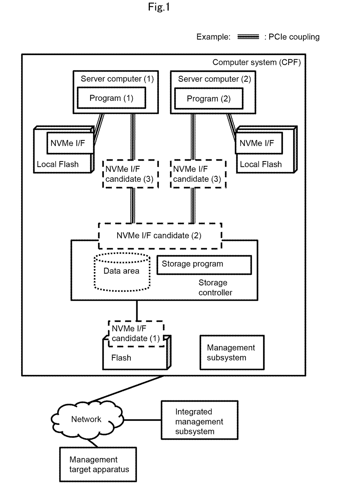
A plurality of server computers shares a virtualized namespace. A storage controller provides a virtual storage area shared by a first server computer and a second server computer. A server computer that is each of the first server computer and the second server computer stores a program that issues an NVM-Express command that is a command conforming to an NVM-Express standard. The program allows the server computer to access the virtual storage area via the PCI-Express by issuing the NVM-Express command specifying a namespace associated with the virtual storage area. The storage controller allocates a storage area in a nonvolatile memory device to the virtual storage area based on the access.

Description

[0001]The present invention relates to a computer system including a nonvolatile memory device.BACKGROUND ART[0002]Flash memory devices (hereinafter referred to as flashes) provide higher I / O (Input / Output) performance than HDDs (Hard Disk Drives). However, in connection with provision of the performance of the flash memory device, conventional SCSI (Small Computer System Interfaces) involves inefficient processing executed in a server by programs such as an OS (Operating System) and device drivers. Thus, providing the high I / O performance of the flash memory device is not easy. NVM-Express (Non-Volatile Memory Express; hereinafter abbreviated as NVMe) described in PTL1 is a standard that specifies the following in order to solve the above-described problem.[0003]This specification defines a streamlined set of registers whose functionality includes:[0004]Indication of controller capabilities[0005]Status for controller failures (command status is processed via CQ directly)[0006]Admin...

Claims


Application Information

Patent Timeline
Patent Type & Authority Applications(United States)
IPC IPC(8): G06F3/06G06F13/42
CPCG06F3/061G06F13/4282G06F2213/0026G06F3/0655G06F3/0631G06F3/0679G06F3/0605G06F3/0644G06F3/067G06F3/0685
Inventor OUCHI, KATSUMISATOYAMA, AIEGUCHI, YOSHIAKI
Owner HITACHI LTD
Learn More