

Quick-change bead former
- Summary
- Abstract
- Description
- Claims
- Application Information
AI Technical Summary
Benefits of technology
Problems solved by technology
Method used
Image

Examples
Example
DETAILED DESCRIPTION OF THE DRAWINGS AND THE PRESENTLY PREFERRED EMBODIMENTS
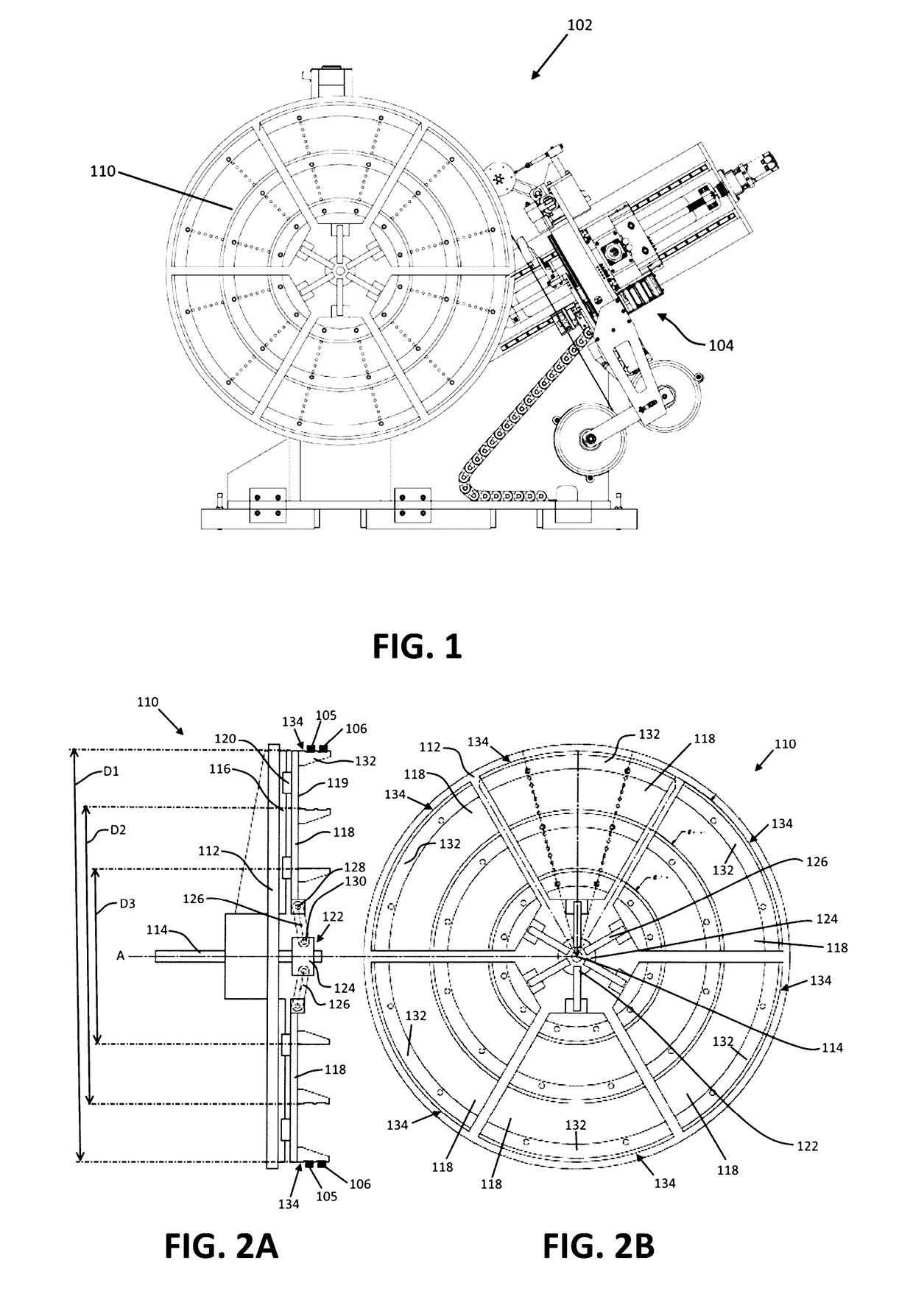
[0020]One embodiment of a tire bead former is depicted by FIG. 1. Referring to FIG. 1, a bead forming system 102 comprises a former 110, which operates to facilitate the supporting (e.g., gripping, holding, securing) and rotating a bead (not shown) during the formation of the bead. Bead forming equipment 104 generally comprises equipment and technology for the formation of an annular bead ring, and may incorporate components from commercially available products such as the SWS-6000 Single Wire Bead Winding System or the TDS-860 Bead Winder System, each of which are manufactured by Bartell Machinery Systems, L.L.C. of Rome, N.Y. Other suitable equipment for forming a tire bead may be used. The bead forming equipment 104 may form either a single-wire bead or a multi-wire (e.g., weftless) bead on the former 110.
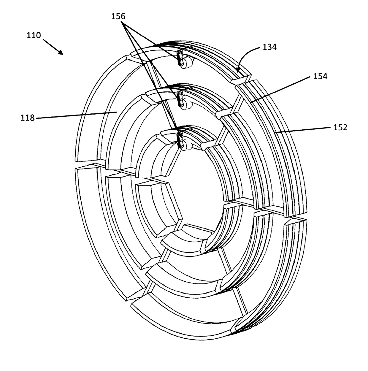
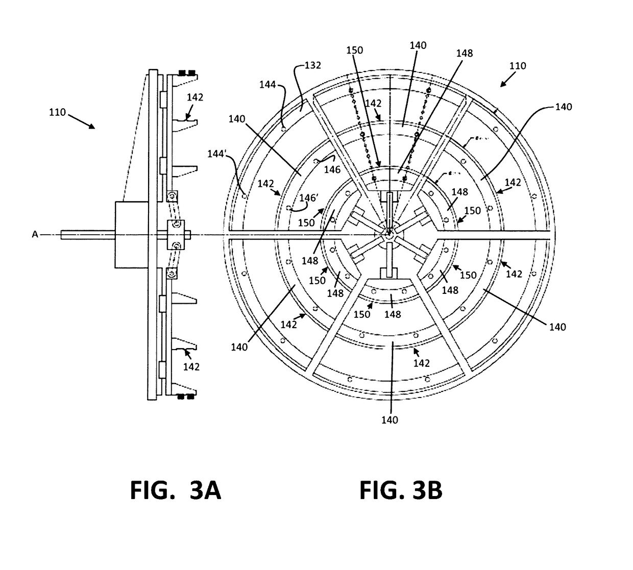
[0021]One embodiment of a former is depicted by FIGS. 2A-2B. Referring to FIGS. 2A-2B, former 110 com...
PUM
 Abstract
Description
Claims
Application Information