Method for designing mold shape and method for producing pressed part

Pending Publication Date: 2021-08-26
JFE STEEL CORP
View PDF0 Cites 0 Cited by
  • Summary
  • Abstract
  • Description
  • Claims
  • Application Information

AI Technical Summary

Benefits of technology

[0019]According to the one aspect of the present invention, the preformed shape can be designed in consideration of all cross-sectional line lengths of the component by simple means, thus enabling manufacturing of a press die effective to p

Problems solved by technology

However, the range of application of PTL 1 is limited only to the flange portions, and cannot be universally used to various component shapes.
However, when press forming into a complicated component shape, cracking and wrinkling can occur in a portion where cross-sectional shape is not taken into consideration.
On the other hand, when trying to design considering all cross sections, it takes more time and more effort to design.
However, designing a three-dimensional shape requires enormous amounts of time and effort unless variables are limited, so that it is not suitable for complicated component shapes.
Furthermore, in the method of PTL 4, it is difficult to find how to form a shape during

Method used


Image

  • Method for designing mold shape and method for producing pressed part
  • Method for designing mold shape and method for producing pressed part
  • Method for designing mold shape and method for producing pressed part

Examples


example 1

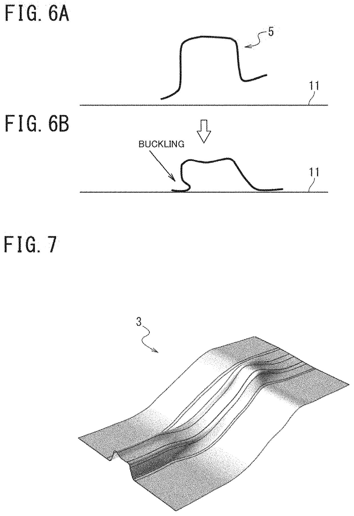
[0084]Example 1 is a case where the same preformed shape 3 as that of FIG. 7 was formed by drawing (first step 2), and then formed into a component shape by stamping in the next step (second step 4).

[0085]In the above Example 1, the metal sheets A to B had no cracks or wrinkles, and the metal sheets C to D had small sheet thickness reduction.

example 2

[0086]In Example 2, the same preformed shape 3 as that of FIG. 8 was formed by drawing (first step 2), and then formed into a component shape by stamping in the next step (second step 4).

[0087]In this Example 2, the metal sheets A to C had no cracks or wrinkles, and the metal sheet D had small sheet thickness reduction.

example 3

[0088]In Example 3, the same preformed shape 3 as that of FIG. 9 was formed by drawing (first step 2), and then formed into a component shape by drawing in the next step (second step 4).

[0089]In the above Example 3, all of the metal sheets A to D had no cracks or wrinkles.

[0090]As shown in Table 2, it has been found that when manufacturing a shape that causes cracks and wrinkles when press formed into the component 5 having the desired three-dimensional shape by the single step, as in Comparative Example 1, press forming based on aspects of the present invention, as in Examples 1 to 3, improves cracks and wrinkles to manufacture the component 5 having the desired three-dimensional shape. In this case, it has also been found that aspects of the present invention enable the preformed shape 3 to be determined by simple means even when manufacturing a component including the component 5 having the complicated three-dimensional shape.


PUM

PropertyMeasurementUnit
Fractionaaaaaaaaaa
Fractionaaaaaaaaaa
Shapeaaaaaaaaaa

Abstract

A preformed shape capable of suppressing occurrence of cracks and wrinkles in a metal sheet can be determined by simple means. A metal sheet is press formed into a three-dimensionally shaped component. A method therefor includes a first step of press forming the metal sheet into an intermediate component having a preformed shape including a shape of the three-dimensionally shaped component crushed under a load applying condition for applying load in a direction in which at least a part of the three-dimensionally shaped component is straightened and a second step of press forming the intermediate component into the three-dimensionally shaped component.

Description

CROSS REFERENCE TO RELATED APPLICATIONS[0001]This is the U.S. National Phase application of PCT / JP2019 / 023719, filed Jun. 14, 2019, which claims priority to Japanese Patent Application No. 2018-126982, filed Jul. 3, 2018, the disclosures of these applications being incorporated herein by reference in their entireties for all purposes.FIELD OF THE INVENTION[0002]The present invention relates to a method for designing a die shape that enables forming with reduced cracking and wrinkling in a metal sheet and a method for manufacturing a pressed component.BACKGROUND OF THE INVENTION[0003]Press forming is one of typical metal processing methods for obtaining a component having a desired three-dimensional shape by sandwiching and pressing a metal sheet between a pair of dies to form the metal sheet, such as a steel sheet, in such a manner as to follow a die shape. Additionally, press forming technologies are used in a wide range of manufacturing fields, such as automobile components, machi...

Claims


Application Information

Patent Timeline
IPC IPC(8): B21D22/26B21D37/10
CPCB21D22/26B21D37/10B21D22/00B21D37/20G06F2113/24G06F30/20B21D22/206
Inventor FUJII, YUSUKEYAMASAKI, YUJI
Owner JFE STEEL CORP
Why Eureka
Try Eureka