Power unit

Active Publication Date: 2006-12-07
MITSUBISHI ELECTRIC CORP
View PDF10 Cites 23 Cited by
  • Summary
  • Abstract
  • Description
  • Claims
  • Application Information

AI Technical Summary

Benefits of technology

[0009] Intended to overcome the aforementioned problems of the prior art, it is an object of the invention to provide an economical power unit with a reduced number of components which need to be replaced and disposed of in case of a failure of any power e

Problems solved by technology

Therefore, even when only one of the power electronic semiconductor devices fails, it is necessary to replace the complete power module including even the properly working semiconductor devices, resulting in an economic loss.
Additionally, a plastic case of the power module incorporating the six power electronic semiconductor units is so large-sized that deformation or a crack tends to occur in t

Method used


Image

  • Power unit
  • Power unit
  • Power unit

Examples


first embodiment

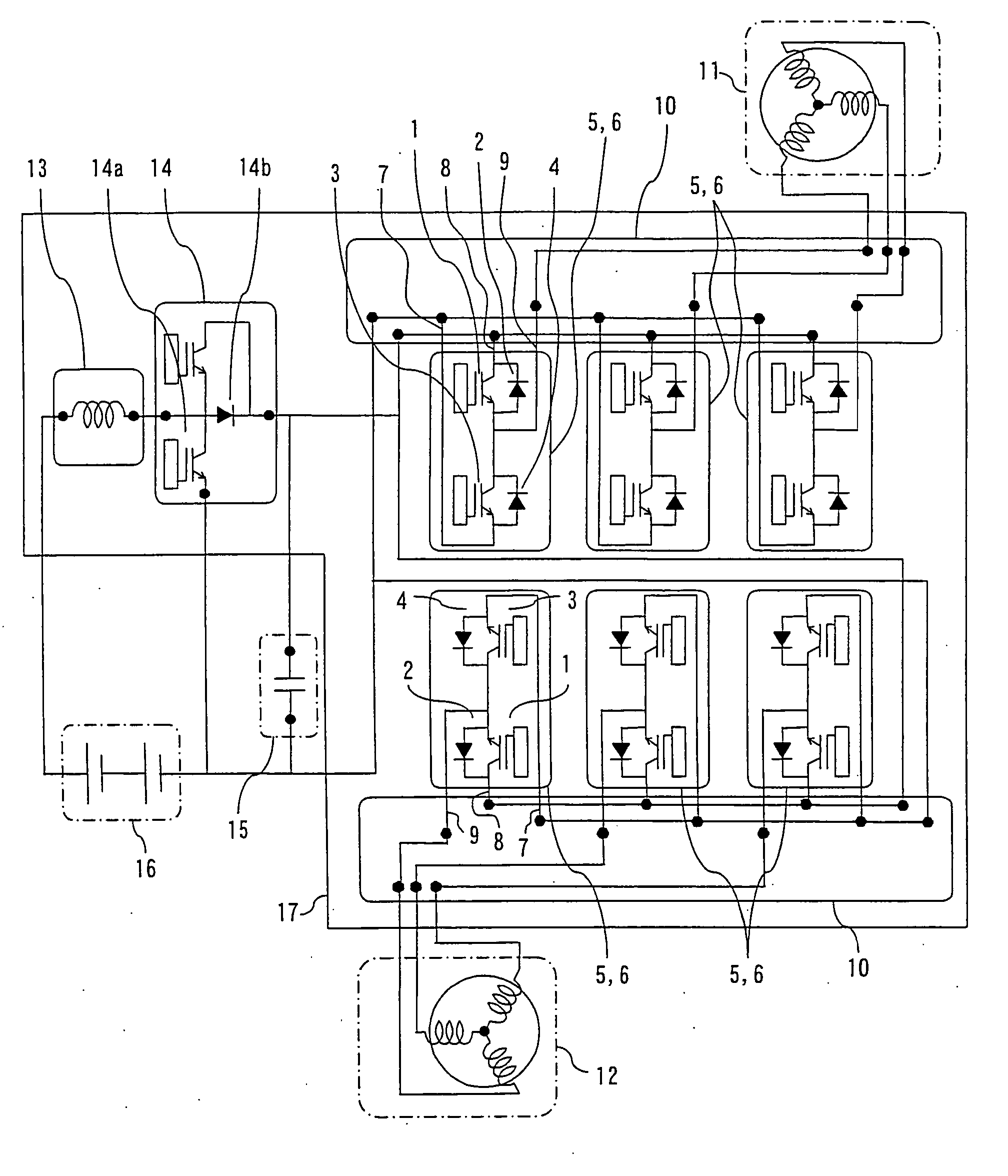
[0025] A power unit mounted on a hybrid vehicle according to a first embodiment of the present invention is described with reference to FIGS. 1 to 3.

[0026] Generally, a hybrid vehicle is equipped with a power converter which works as an inverter for converting DC power fed from an onboard battery into AC power to drive a motor and as a converter (rectifier) for converting AC power produced by transforming kinetic energy of the vehicle into electrical energy by a generator during braking into DC power to charge the battery. In this embodiment, the hybrid vehicle is provided with a pair of rotating electric machines 11, 12 each of which can be operated either as a motor or as a generator. In one form of the invention, one of these rotating electric machines 11, 12 is run as a motor while the other is run as a generator. In another form of the invention, both of the rotating electric machines 11, 12 are operated as motors or as generators at the same time. This kind of rotating electr...

second embodiment

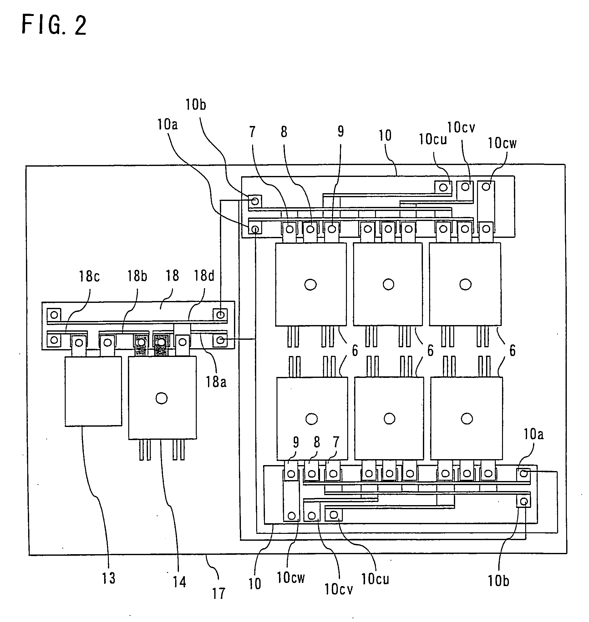
[0050]FIG. 5 is a plan view of a power unit according to a second embodiment of the invention. While the inductor 13 and the power module 14 constituting the DC-DC converter are connected to the terminal block 18 provided separately from the terminal blocks 10 to which the power modules 6 are connected in the aforementioned first embodiment, the inductor 13 and the power module 14 are arranged as illustrated in FIG. 5 in the power unit of the second embodiment.

[0051] In this embodiment, one of two terminal blocks 10 to which three each power modules 6 are connected is elongated, and the inductor 13 and the power module 14 together constituting a DC-DC converter are connected to the elongated terminal block 10. A P-side conductor 10a, an N-side conductor 10b, three rotating-machine-side phase conductors 10cu, 10cv, 10cw and two conductors 10d, 10e are embedded in this elongated terminal block 10. The inductor 13 and the power module 14 are arranged side by side with main terminals t...

third embodiment

[0053]FIG. 6 is a circuit diagram showing an internal circuit configuration of a power unit according to a third embodiment of the invention, and FIG. 7 is a plan view of the power unit of the third embodiment showing in particular an arrangement of constituent components thereof, in which elements equivalent to those of the first embodiment are designated by the same reference numerals.

[0054] While the power unit is provided with the two terminal blocks 10 for the rotating electric machines 11, 12 and three each power modules 6 are connected to the individual terminal blocks 10 in the aforementioned first embodiment, the power unit of the third embodiment is provided with only one terminal block 10 and all six power modules 6 are connected to this terminal block 10. As illustrated in FIGS. 6 and 7, three each power modules 6 are arranged side by side on opposite sides of the terminal block 10 such that main terminals 7, 8, 9 of the three each power modules 6 arranged side by side ...


PUM


Abstract

A power unit includes a plurality of power modules for controlling individual phases of a pair of rotating electric machines and a heat sink on which the power modules are mounted. Each of the power modules includes a metal block, four power electronic semiconductor devices which are heat-generating elements mounted on the metal block with electrically conductive device bonding layers placed in between, and a plastic case. The plastic case is made of a plastic material sealing the power electronic semiconductor devices and the metal block in a single package with leads connected to top- and bottom-side electrodes of the power electronic semiconductor devices extending outward from the plastic case.

Description

BACKGROUND OF THE INVENTION [0001] 1. Field of the Invention [0002] The present invention relates generally to a power unit used as a power converter for controllably driving an electric motor or a generator mounted on a mobile unit, such as a motor vehicle, and more particularly, to a power unit including power modules which incorporate power electronic semiconductor devices. [0003] 2. Description of the Background Art [0004] Hybrid vehicles have recently been marketed in automotive industry. The hybrid vehicles are typically equipped with a power converter which converts direct current (DC) power fed from an onboard battery into alternating current (AC) power to drive a motor and converts AC power produced by transforming kinetic energy into electrical energy by a generator during braking into DC power to charge the battery. [0005] As an example, Japanese Patent Application Publication No. 2003-204606 discloses a conventional hybrid vehicle provided with a pair of rotating electri...

Claims


Application Information

Patent Timeline
IPC IPC(8): H02P9/04
CPCH02M7/003H02M7/5387H02M2001/007H01L2924/181H01L2224/48091H01L2224/48247H01L2224/73265H01L2924/00012H01L2924/00014H01L2924/13055H02M1/007H01L2924/00
Inventor YAMABUCHI, HIROSHIKURAMOTO, YUJIKIMURA, TORU
Owner MITSUBISHI ELECTRIC CORP
Why Eureka
Try Eureka