Cover for writing instrument

Inactive Publication Date: 2017-04-20
IMBESI ANITA
View PDF9 Cites 4 Cited by
  • Summary
  • Abstract
  • Description
  • Claims
  • Application Information

AI Technical Summary

Benefits of technology

[0019]In yet another embodiment, the top further includes at least one barb extending upwardly therefrom, and the decorative element further includes a flower ovary and a plurality of petals. The flower ovary is secured to the at least one barb and the plurality of petals are disposed circumferentially about the base. Preferably, the scented medium is a perfume or an essential oil. However, is should be appreciated that the scented medium ca

Problems solved by technology

There were other disadvantages associated with their use, including a lengthy preparation time.
However, early fountain pen models were plagued by ink spills and other failures that left them impractical and hard to sell.
One problem with present decorative covers is that the decorative element is bound directly to the writing instrument via an adhesive, such as tape.
Another problem with present decorative covers is that the decorative cover and/or decorative ele

Method used


Image

  • Cover for writing instrument
  • Cover for writing instrument
  • Cover for writing instrument

Examples


first embodiment

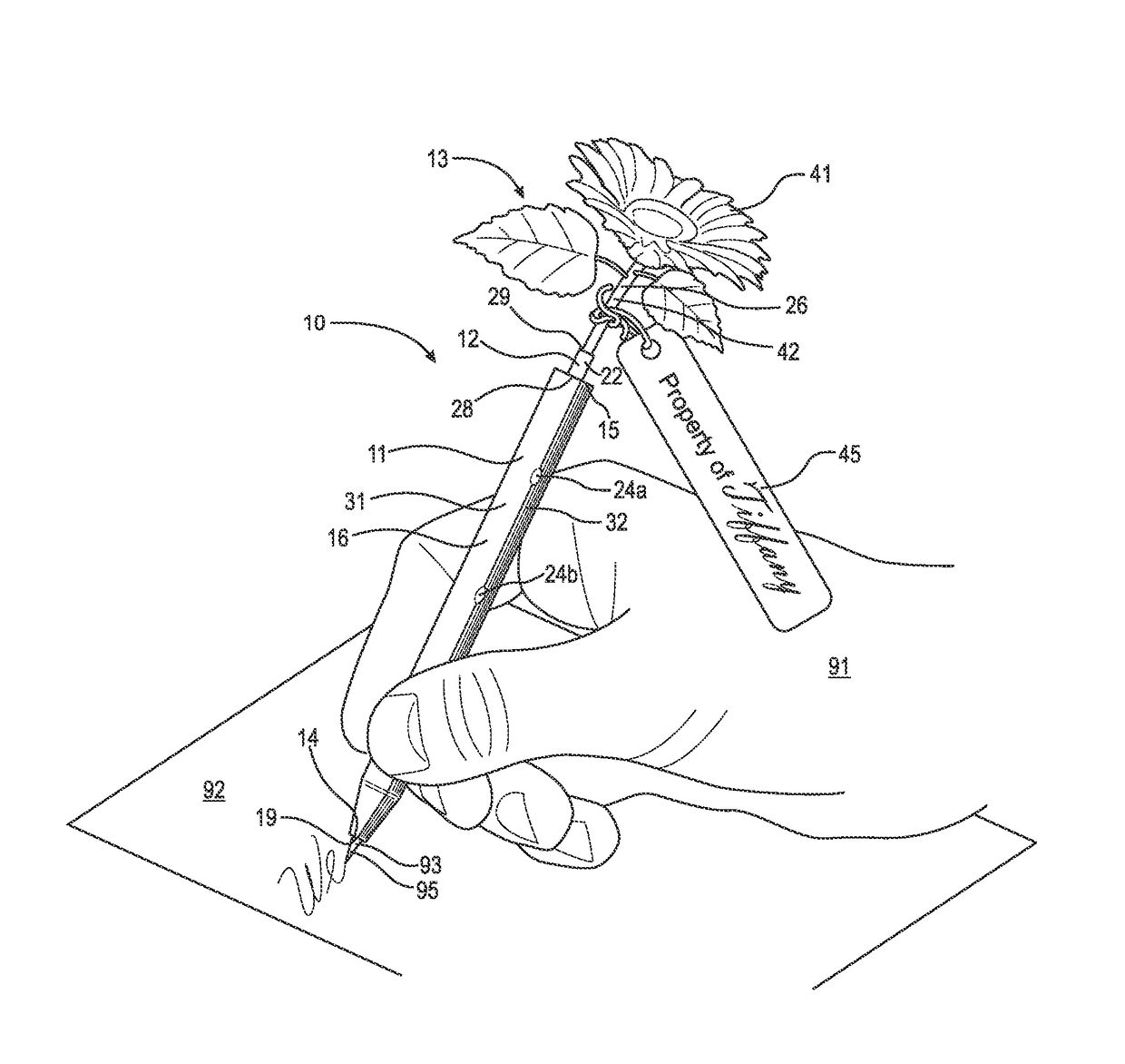
[0039]Adverting now to the figures, FIG. 1 is cover 10 of the present invention for a writing instrument. Cover 10 broadly includes body 11, protrusion 12, and decorative element 13. As shown in FIG. 1, body 11 in a closed position, having pen 93 disposed within space 20. Body 11 is held by hand 91 and being used to write on paper 92. Hand 91 grasps outer surface 16 of body 11. Preferably, cover 10 includes tag 45 secured to body 11 via rope 46.

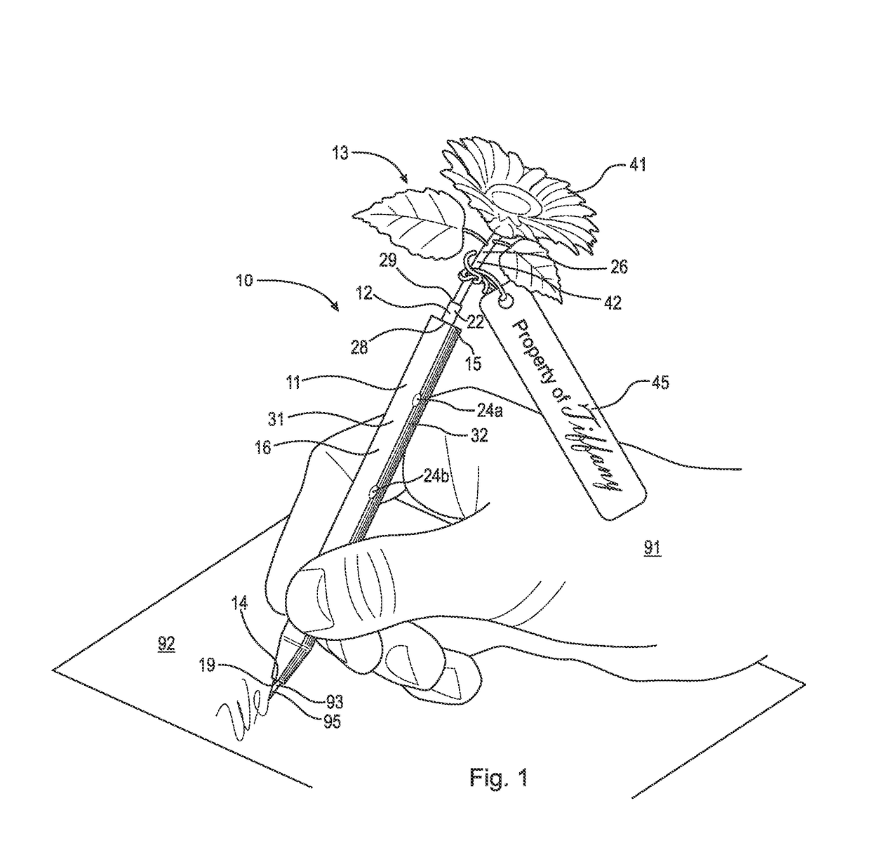
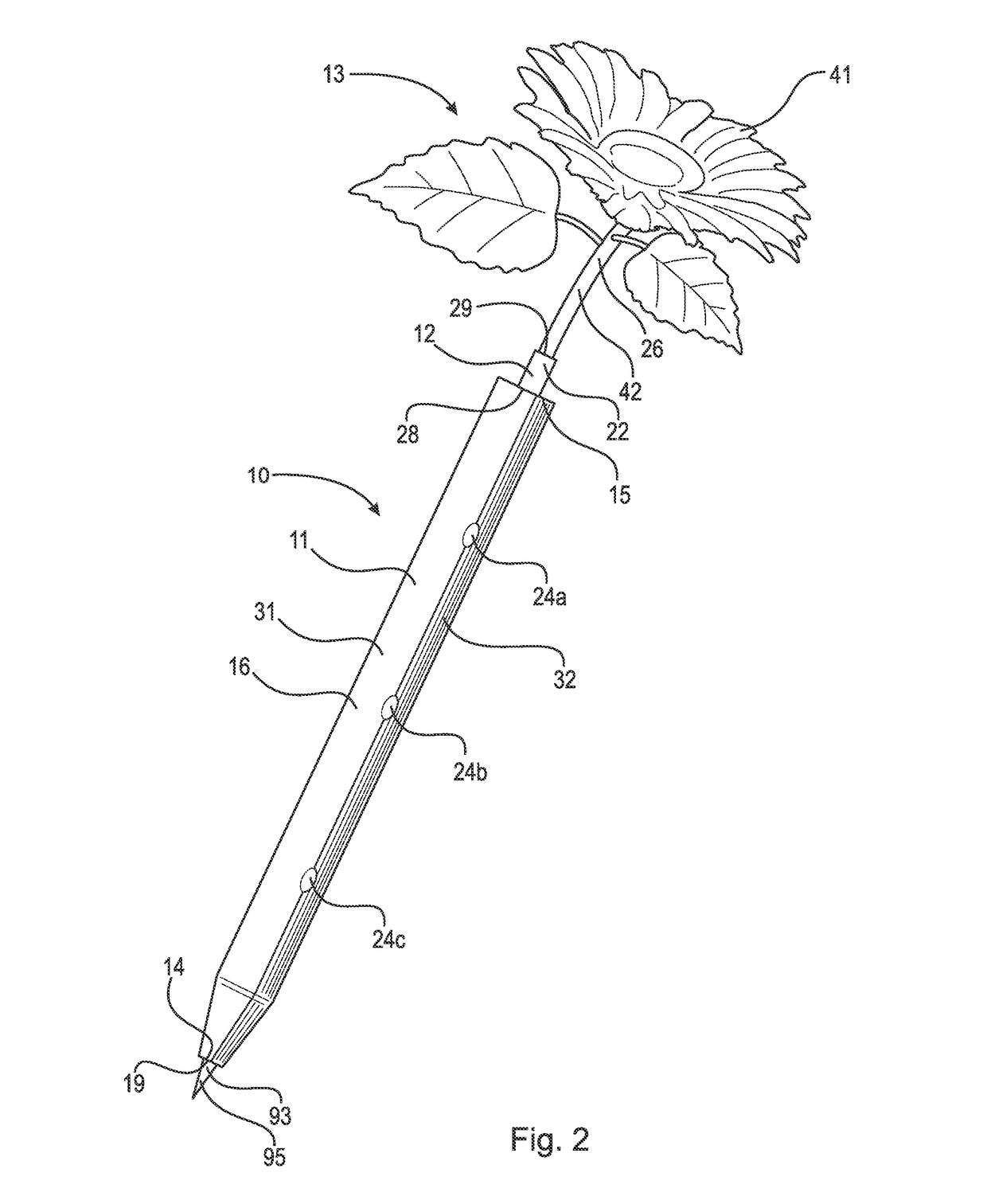
[0040]FIG. 2 is a front perspective view of cover 10, shown with paper 92 removed.

[0041]FIG. 3 is a front elevational view of the cover 10, shown with pen 93 removed and FIG. 4 is a corresponding rear elevational view of cover 10.

[0042]FIG. 5 is a bottom plan view of cover 10 and FIG. 6 is the corresponding top plan view of cover 10, shown with the decorative element removed.

[0043]FIG. 7 is a front perspective view of cover 10, shown in an open position.

[0044]As shown in FIGS. 1 through 7, in a first embodiment, body 11 has first end 14, seco...

fourth embodiment

[0048]FIG. 10 is a front perspective view of cover 10, shown in an open position, having pencil 94 disposed within space 20.

third embodiment

[0049]As shown in FIG. 10, in the third embodiment, body 11 further includes slot 35, lever 36, and disc 38. Lever 36 is disposed within slot 35 and is operatively arrange to move longitudinally along slot 36 in order to accommodate writing instruments of varying heights. Thus, as shown, tip 96 of pencil 94 can be sharpened, causing the height of pencil 94 to decrease. As the height of pencil 94 decreases, lever 36 is depressed longitudinally along slot 35 to prevent the pencil from sliding upward within body 11 when tip 96 is pressed. Preferably, disc 38 is integral with lever 36 and contacts pencil 94 to prevent pencil 94 from being displaced within space 20 as the length of pencil 94 decreases. Similar to FIG. 9, FIG. 10 includes soccer ball 43 and tubular extension 44 as decorative element 13 and extension member 26, respectively.

[0050]FIG. 11 is an exploded view of an embodiment of decorative element 13, in particular flower 41, shown having housing 56 in an open position and f...


PUM


Abstract

A cover for a writing instrument having a body, a protrusion, and a decorative element. The body has a first end, a second end, an inner surface, an outer surface, and a space bounded by the inner surface. The space is operatively arranged to hold a writing instrument. The protrusion has a first end and a second end, where the first end is secured to and extends upwardly from the second end of the body. The decorative element has an extension member extending downwardly, where the extension member is secured to the second end of the protrusion. The body further includes at least one hinge means extending longitudinally about the body and at least one latch.

Description

FIELD OF THE INVENTION[0001]The invention broadly relates to a cover for a writing instrument, and in particular, to a removable cover having a decorative element secured to an end of the writing instrument.BACKGROUND OF THE INVENTION[0002]Writing instruments are well known in the art and have been around for thousands of years. The earliest writing instruments that resembled a pen and paper were developed by the Greeks. They developed a writing instrument, made of metal, bone or ivory, to mark upon wax-coated tablets. The Romans created a reed-pen from the hollow tubular-stems of marsh grasses, such as the bamboo plant. They converted bamboo stems into a primitive form of a fountain pen.[0003]They cut one end into the form of a pen nib or point, filled the stem with an ink, and squeezed the reed to force fluid to the nib.[0004]The writing instrument that proliferated for the longest period in history, over one-thousand years, was the quill pen. The quill pen was introduced around 7...

Claims


Application Information

Patent Timeline
IPC IPC(8): B43K31/00B43K23/00B43K29/00
CPCB43K31/00B43K23/00B43K29/00B43K29/004B43K23/001
Inventor IMBESI, ANITA
Owner IMBESI ANITA
Why Eureka
Try Eureka