Anti-roll bar device with variable rigidity

a technology of variable rigidity and anti-roll bar, which is applied in the direction of interconnection systems, vehicle springs, vehicle components, etc., can solve the problems of vehicle body tilting or shaking up and down, suspension system force, and slight height difference between the two suspension systems

Active Publication Date: 2017-04-20
METAL INDS RES & DEV CENT
View PDF0 Cites 9 Cited by
  • Summary
  • Abstract
  • Description
  • Claims
  • Application Information

AI Technical Summary

Benefits of technology

[0007]The main objective of the present invention is to provide an anti-roll

Problems solved by technology

When the vehicle is in cornering, the vehicle is tilted due to the centrifugal force, and the suspension systems will be forced.
However, when the vehicle passes a bumpy terrain, a slight height difference is continuously formed between the two suspension systems because of the bumpy road conditions.
If

Method used


Image

  • Anti-roll bar device with variable rigidity
  • Anti-roll bar device with variable rigidity
  • Anti-roll bar device with variable rigidity

Examples


Embodiment Construction

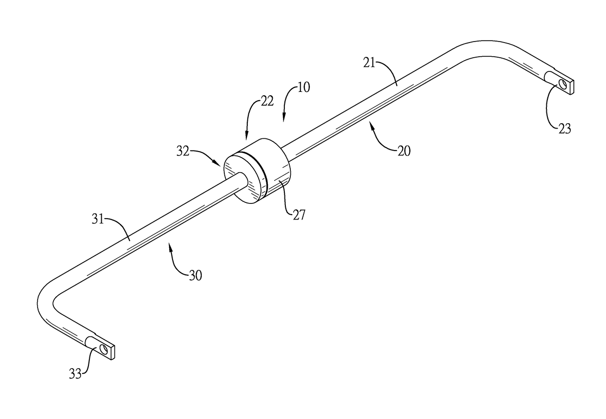
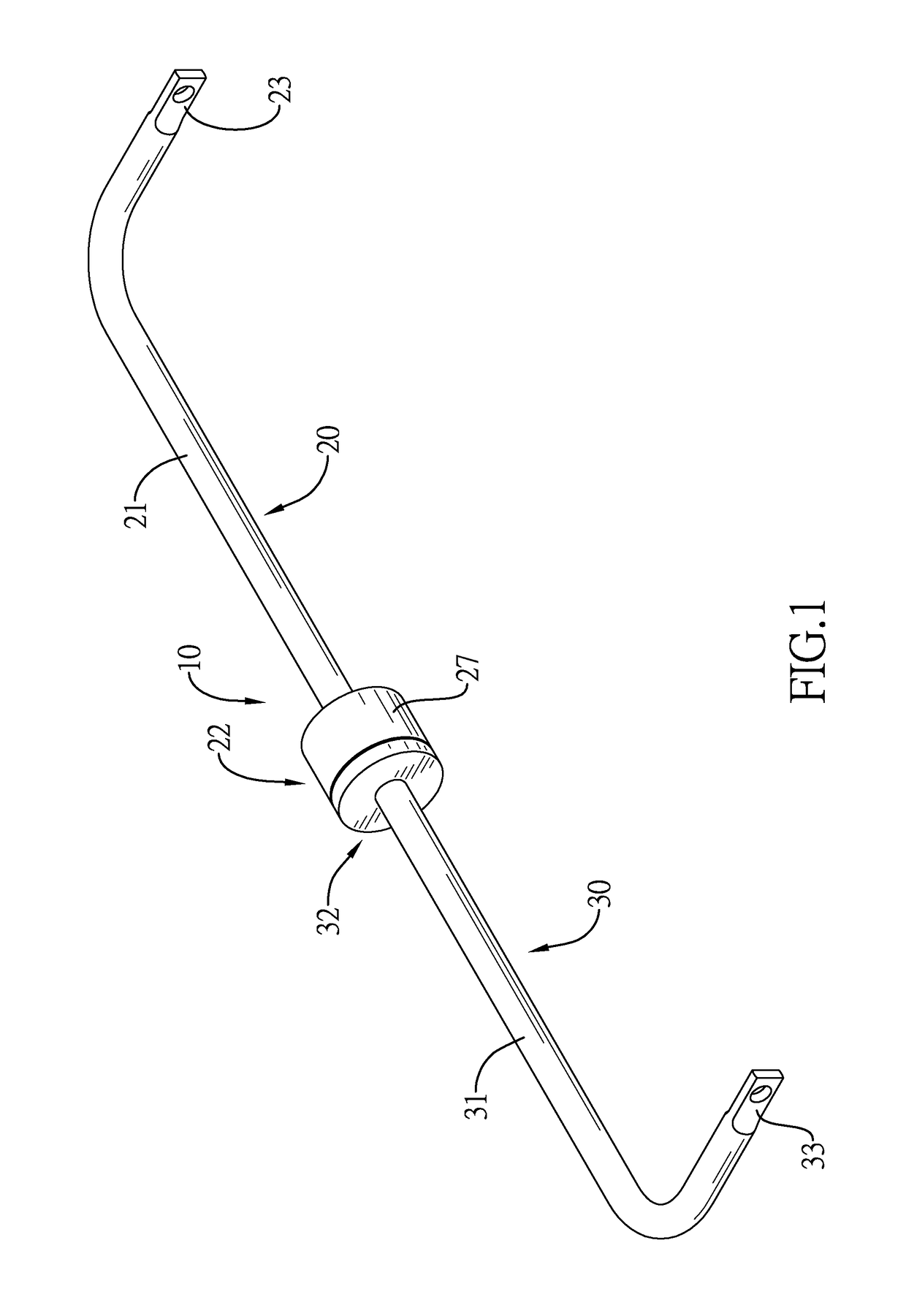
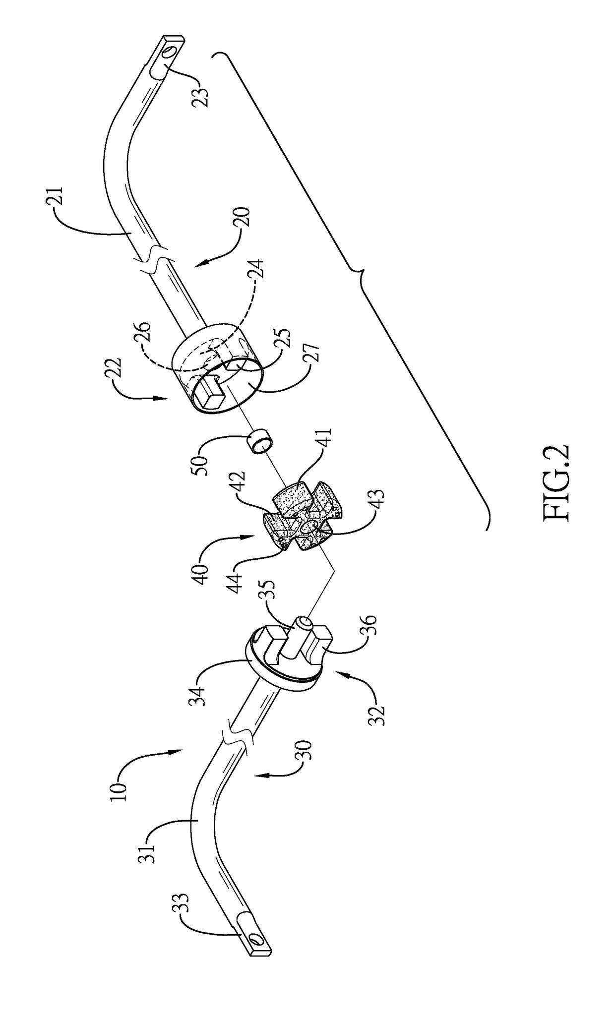
[0023]With reference to FIGS. 1, 2, and 4, a first embodiment and a second preferred embodiment of an anti-roll bar device 10 with a variable rigidity in accordance with the present invention comprises a first arm assembly 20, a second arm assembly 30, a variable rigidity unit 40, 40A, and at least one bearing 50.

[0024]With reference to FIGS. 2 and 4, the first arm assembly 20 comprises a first bar 21 and a first joining module 22. The first bar 21 is bent and comprises a first connecting portion 23 formed on an end of the first bar 21. The first joining module 22 is mounted on an end of the first bar 21 at a position opposite the first connecting portion 23, and comprises a first base 24 and multiple first joining units 25, 25A. The first base 24 comprises a recess 26 recessed in a middle of the first base 24. The first joining units 25, 25A are mounted on a side of the first base 24 opposite the first bar 21, and are disposed around the recess 26.

[0025]With reference to FIGS. 2 to...


PUM


Abstract

An anti-roll bar device with a variable rigidity has a first arm assembly having multiple first joining units, a second arm assembly having multiple second joining units, and a variable rigidity unit mounted between the first arm assembly and the second arm assembly and having multiple abutment portions and a variable rigidity coefficient. The first and second joining units are staggered with each other annularly and abut the abutment portions. When a vehicle passes a bumpy terrain, a slight force is exerted on the variable rigidity unit and is absorbed by the variable rigidity unit, such that the vehicle can be kept from tilting and shaking up and down. When the vehicle is in cornering, a larger force is exerted on the variable rigidity unit to increase a rigidity of the variable rigidity unit, such that the variable rigidity unit can transfer torques to keep the vehicle from tilting.

Description

BACKGROUND OF THE INVENTION[0001]1. Field of the Invention[0002]The present invention relates to an anti-roll bar device, and more particularly to an anti-roll bar device with a variable rigidity.[0003]2. Description of Related Art[0004]When a vehicle is in cornering, a centrifugal force will lead to a vehicle body of the vehicle to tilt, and the vehicle may be capsized easily, so an anti-roll bar device is mounted between two suspension systems of two wheels, and two ends of the anti-roll bar device are mounted on bottoms of the suspension systems. Multiple fixing units are mounted on the anti-roll bar device and are fixed on the vehicle body, such that the anti-roll bar device can be fixed on the vehicle body.[0005]When the vehicle is in cornering, the vehicle is tilted due to the centrifugal force, and the suspension systems will be forced. The suspension system which is located at an outer side of the vehicle will be compressed, and the other suspension system which is located a...

Claims


Application Information

Patent Timeline
IPC IPC(8): B60G21/055
CPCB60G21/0558B60G2206/73B60G2204/82B60G2206/427B60G2200/34B60G21/055B60G2202/135B60G2800/0122
Inventor YANG, CHUN-PINLIN, CHIA PINHSU, WEI LUN
Owner METAL INDS RES & DEV CENT
Why Eureka
Try Eureka