Method for operating an electronic brake system

a technology of electronic brakes and brake systems, applied in the direction of brake systems, control devices, etc., can solve the problems of tilting when cornering, and achieve the effect of improving stability control

Active Publication Date: 2017-04-20
ZF CV SYST EURO BV
View PDF1 Cites 1 Cited by
  • Summary
  • Abstract
  • Description
  • Claims
  • Application Information

AI Technical Summary

Benefits of technology

[0005]One object of the present invention is to provide a method for operating an electronic brake system with the possibility of improved stability control.

Problems solved by technology

Owing to the load, utility vehicles can have such a high center of gravity that tilting can occur when cornering.

Method used


Image

  • Method for operating an electronic brake system
  • Method for operating an electronic brake system
  • Method for operating an electronic brake system

Examples


Embodiment Construction

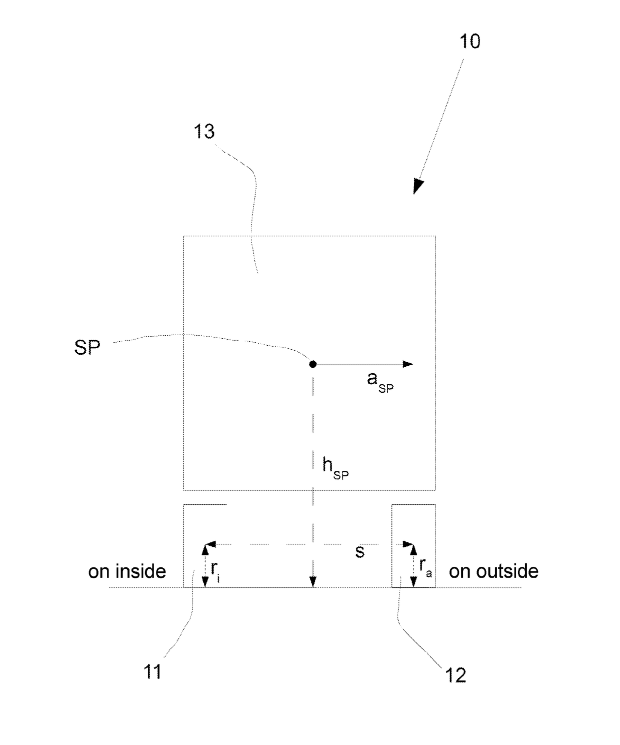
[0024]Referring to FIG. 1, the vehicle 10 can be a traction vehicle or a trailer vehicle and is equipped in a manner known per se with compressed air brakes, wheel speed sensors, an electronic brake system, a brake control unit with a transverse acceleration sensor and with travel sensors or bellows pressure sensors for determining an axle load.

[0025]Cornering is assumed, with the wheel 11 as a wheel on the inside of the bend and the wheel 12 as a wheel on the outside of the bend. In this context, a transverse acceleration aSP acts on a center of gravity SP of the vehicle 10. The center of gravity SP is at a height hSP.

[0026]The center of gravity SP is assumed here to be a location of an axle load acting on the wheels 11, 12. The axle load results in tire deformation at the wheels 11, 12, which tire deformation depends on the transverse acceleration aSP which is occurring. The effective tire radius ra of the wheel 12 on the outside of the bend decreases, while the effective tire rad...


PUM


Abstract

A method for operating an electronic brake system in a vehicle having at least two tires on an axle, wherein the vehicle has a center of gravity (SP) with a height (hSP), is disclosed. According to the method, the height (hSP) of the center of gravity (SP) is calculated and used as a parameter by the electronic brake system. An electronic control unit, an electronic brake system, and a vehicle including the same for carrying out the method are also disclosed.

Description

CROSS-REFERENCE TO RELATED APPLICATIONS[0001]This application is the National Stage of International Application No. PCT / EP2015 / 001053, filed on 22 May 2015, which claims priority to and all advantages of German Patent Application No. 10 2014 008 562.7, filed on 11 Jun. 2014, the content of which is hereby incorporated by reference.FIELD OF THE INVENTION[0002]The invention relates to a method for operating an electronic brake system in a vehicle having at least two tires on one axle, wherein the vehicle has a center of gravity SP with a height hSP. Furthermore, the invention relates to an electronic brake system and to an electronic control unit for carrying out the method, and to a vehicle having an electronic control unit and / or brake system.BACKGROUND OF THE INVENTION[0003]Utility vehicles are typically equipped with pneumatically activated brakes. The actuation is carried out by two systems, specifically primarily electronically and secondarily pneumatically. Owing to the electr...

Claims


Application Information

Patent Timeline
Patent Type & Authority Applications(United States)
IPC IPC(8): B60T8/1755B60T8/172
CPCB60T2250/06B60T8/17551B60T2240/06B60T2201/16B60T2240/04B60T8/172B60T8/17554B60T8/58B60W2040/1315
Inventor CZAJA, DANIELSTENDER, AXELTREICHEL, THOMASWOLF, MARKUS
Owner ZF CV SYST EURO BV
Why Eureka
Try Eureka