Lighting fixture and related control method

a technology of light fixture and control method, applied in the field of light fixture, can solve the problem of limited excursion of moving elements, and achieve the effect of less drawbacks

Active Publication Date: 2017-04-20
CLAY PAKY
View PDF2 Cites 3 Cited by
  • Summary
  • Abstract
  • Description
  • Claims
  • Application Information

AI Technical Summary

Benefits of technology

[0007]It is therefore an object of the present invention to provide a lighting fixture to achieve spectacular effects having less drawbacks than those of the prior art.

Problems solved by technology

In fact, in this case the movable element excursion can be limited by suitably configuring a control unit of the lighting fixture.

Method used


Image

  • Lighting fixture and related control method
  • Lighting fixture and related control method
  • Lighting fixture and related control method

Examples


Embodiment Construction

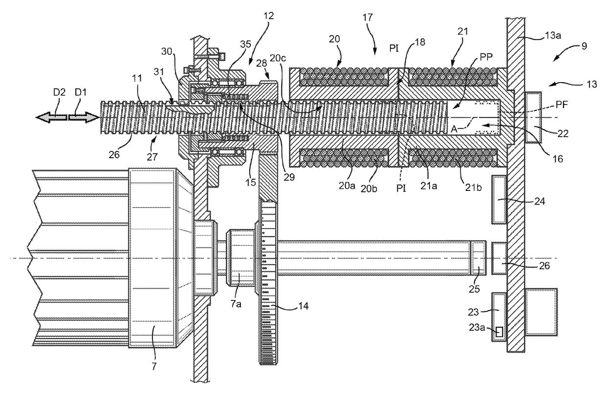
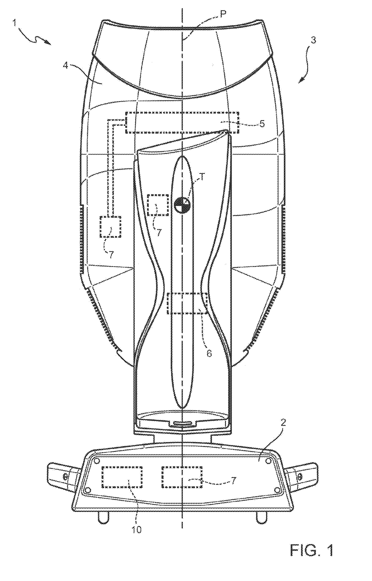
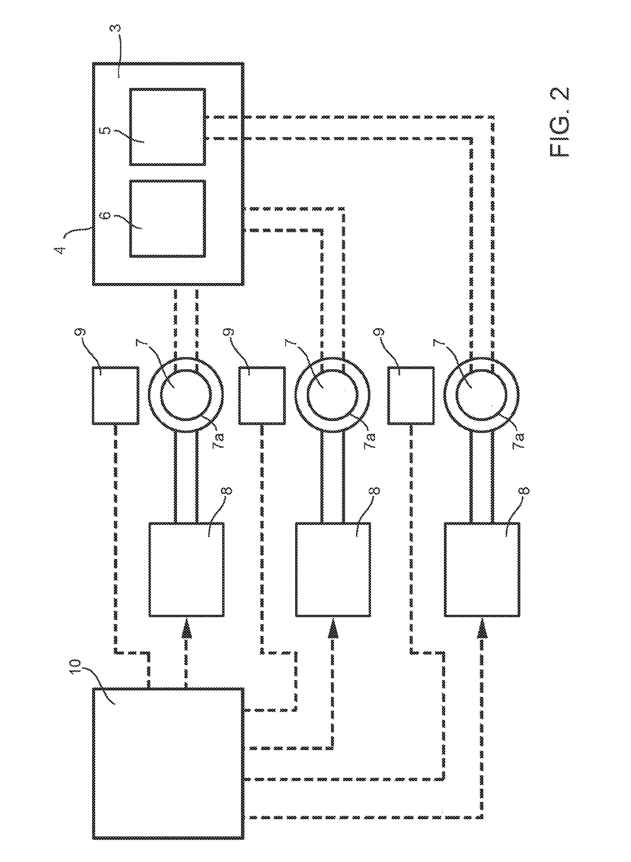
[0041]FIG. 1 indicates with the reference number 1 a lighting fixture to achieve spectacular effects comprising a base 2; a plurality of movable elements 3; a lighting unit 6 (FIG. 2) for generating a light beam along an optical axis; a plurality of rotary actuators 7 for moving the movable elements 3; a plurality of driving circuits 8 connected to the rotary actuators 7; a position sensor 9 (FIG. 2) for each rotary actuator 5 and a control unit 10. Each movable element 3 is configured to move along an axis or to rotate about an axis between a first initial position and a first final position. The movable elements 3 are defined, for example, by a head 4, which rotates relative to a base 2 and which houses the lighting unit 6, or by a zoom lens 5 housed in the head 4, which moves with respect to the lighting unit 6.

[0042]With reference to FIGS. 1 and 2, the head 4 is mechanically coupled to two of the rotary actuators 7 to rotate, respectively, about a pan axis P and a tilt axis T.

[0...


PUM


Abstract

A lighting fixture comprising:
    • at least one movable element;
    • at least one rotary actuator coupled to the movable element to move the movable element;
    • a position sensor comprising a linear transducer coupled to the rotary actuator and comprising a slider; wherein the linear transducer is configured to move the slider along a path by a displacement proportional to an angular displacement of the rotary actuator; the position sensor comprising a detection module for detecting the position of the slider along the path; the position sensor being configured to calculate the absolute displacement of the movable element based on the detected position of the slider along the path; preferably the path extending along an axis.

Description

TECHNICAL FIELD[0001]The present invention relates to a lighting fixture and in particular a stage projector.[0002]A stage projector is employed in the entertainment industry to achieve spectacular effects by using light beams.BACKGROUND OF THE INVENTION[0003]Generally, a lighting fixture comprises at least one movable element; a lighting unit for generating a light beam; at least one rotary actuator for moving the at least one movable element; and at least one rotary actuator driving circuit for driving the electric motor. The movable element can be defined by a head of the lighting fixture, which houses the lighting unit and which is moved by two rotary actuators, one for the pan movement and another for the tilt movement; or it can be defined by another element housed within the head and movable with respect to the head thanks to a rotary actuator, e.g. the movable element can be a zoom lens housed in the head of the projector and movable along a zoom axis with respect to the lig...

Claims


Application Information

Patent Timeline
Patent Type & Authority Applications(United States)
IPC IPC(8): F21V21/14F16H25/20G01D5/14F21V14/06G01D5/20
CPCF21V21/14F21V14/06G01D5/20F16H2025/2081F16H25/2015F21W2131/406G01D5/142F21S8/00F21V21/15F21V23/003F21V23/0442F21W2131/105F21V23/0492G01D5/04H02K7/06H02K11/215H02K11/225H02K11/25G01D5/145G01D2205/22
Inventor VENTURATI, CARLO
Owner CLAY PAKY
Why Eureka
Try Eureka