Automated alignment of optics within a flow cytometer

Active Publication Date: 2017-04-27
ESSEN INSTR INC D B A ESSEN BIOSCIENCE INC
View PDF2 Cites 1 Cited by
  • Summary
  • Abstract
  • Description
  • Claims
  • Application Information

AI Technical Summary

Benefits of technology

[0005]Accordingly, a method and a flow cytometer system in which a light path is optimally aligned to direct light from a light source to a flow cell of a flow cytometer instrument are provided. In this regard, the flow cytometer may include an orientable mirror disposed in the light path between the light source and the flow cell. By changing an orientation of the mirror through a sequence of different orientations, an optimal orientation of the mirror may be determined. Since vibrati

Problems solved by technology

Since vibration, thermal expansion and contraction, and other forces that may effect the alignment of various optical components in the flow cytometer instrument can continue to negatively impact optimal performance of the flow cytometer during its use

Method used


Image

  • Automated alignment of optics within a flow cytometer
  • Automated alignment of optics within a flow cytometer
  • Automated alignment of optics within a flow cytometer

Examples


Example

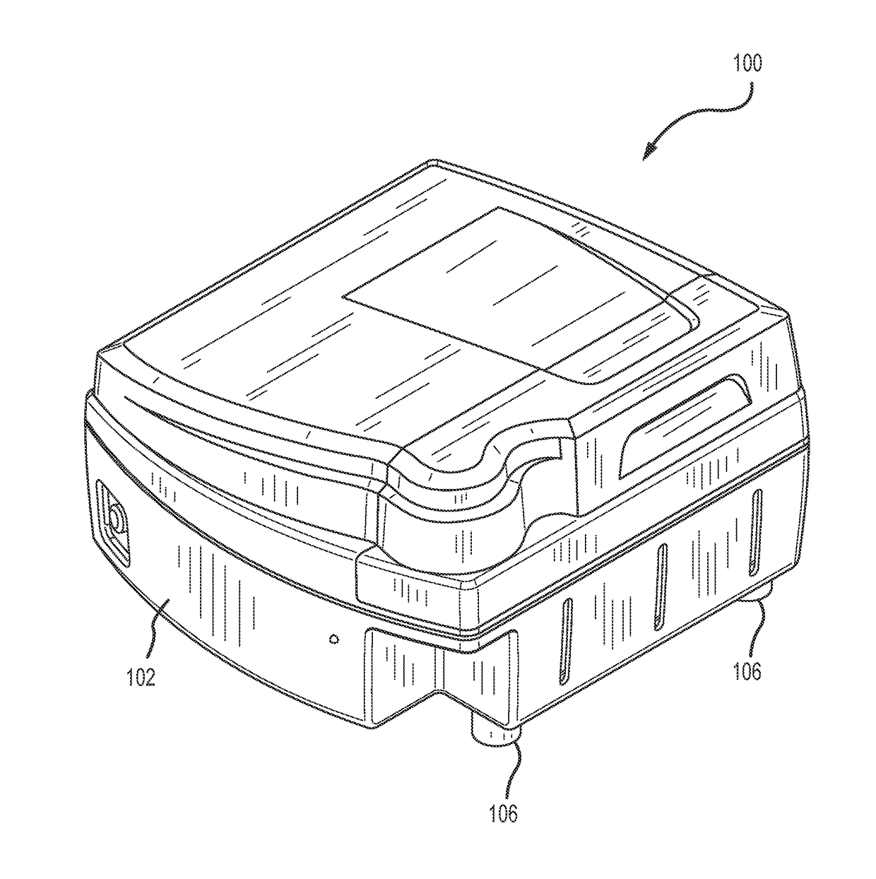
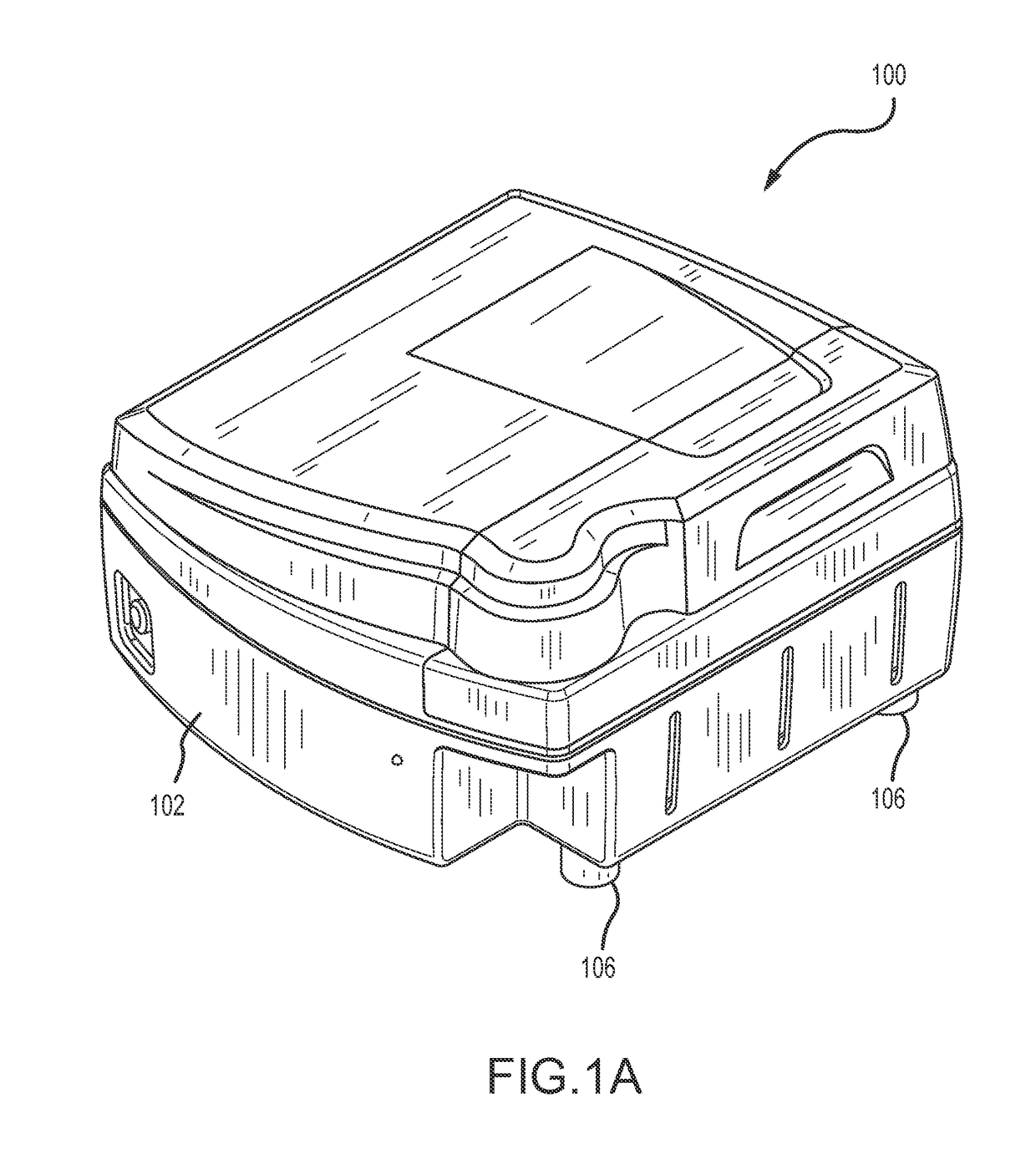
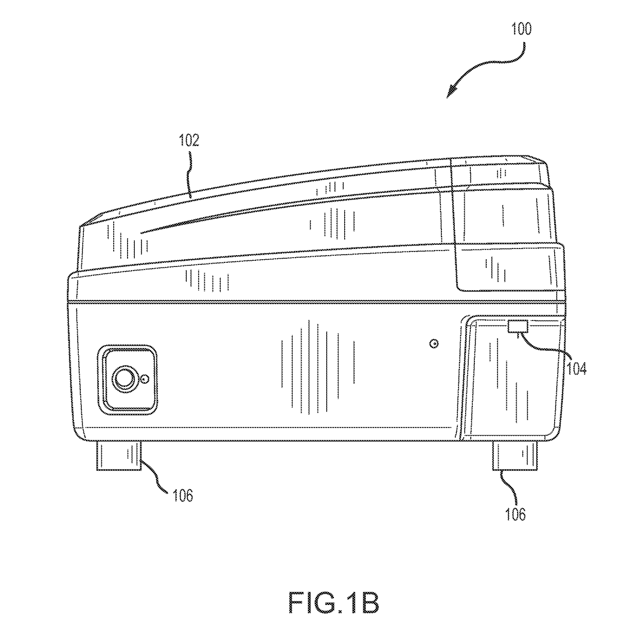
[0015]FIGS. 1A-1B show a flow cytometer 100 that includes flow cytometry componentry contained within a protective enclosure 102. Fluid samples may be introduced into the flow cytometer 100 for flow cytometry investigation through a sample inlet 104. The flow cytometer 100 includes support pads 106 on which the weight of the enclosure 102 and contents within the enclosure 102 are supported. Advantageously, the support pads 106 may be of a material that provides significant vibration isolation to the enclosure 102, and to contents within the enclosure 102, from ambient environment vibrations that may be transmitted through a shelf, table or other surface on which the flow cytometer 100 may be situated during use. The support pads 106 may, therefore, provide a vibration isolation structure that provides a vibration propagation barrier to the enclosure 102 and contents within the enclosure 102. For example, the support pads 106 may be of a polymeric composition that provides a vibratio...


PUM


Abstract

A method and a flow cytometer system in which a light path is aligned to optimally direct light from a light source to a flow cell of a flow cytometer instrument are provided. The flow cytometer may include an orientable mirror disposed in the light path between the light source and the flow cell. By changing an orientation of the mirror through a sequence of different orientations, an optimal orientation of the mirror may be determined, and the mirror may be oriented accordingly before proceeding to conduct a flow cytometry investigation.

Description

CROSS-REFERENCE TO OTHER APPLICATIONS[0001]This application is related to a concurrently filed international patent application under the Patent Cooperation Treaty entitled “FLOW CYTOMETER WITH OPTICAL SYSTEM ASSEMBLY” filed with the U.S. Patent and Trademark office as receiving office, assigned international application number PCT / US2015 / 033795 and further identified as attorney docket number 50911-00031, and this application is related to U.S. provisional patent application entitled “FLOW CYTOMETER WITH OPTICAL SYSTEM ASSEMBLY” filed Jun. 5, 2014, assigned application Ser. No. 62 / 008,401 and further identified by attorney docket number 50911-00020, the entire contents of each such referenced application being incorporated herein by reference. This application also claims the benefit of U.S. provisional patent application Ser. No. 62 / 008,371 entitled “AUTOMATED ALIGNMENT OF OPTICS WITHIN A FLOW CYTOMETER” filed Jun. 5, 2014, and further identified by attorney docket number 50911-00...

Claims


Application Information

Patent Timeline
IPC IPC(8): G01N15/14G01N21/64
CPCG01N15/1436G01N2021/6439G01N21/6428G01N15/1434G01N15/1459G01N2015/1006
Inventor SMOLAK, ANDREW W.TENENT, ERICA DAWSONROWLEN, KATHY L.WILSON, GARRETT S.CONVERSE, CHRISTOPHER H.TOTH, EVAN M.
Owner ESSEN INSTR INC D B A ESSEN BIOSCIENCE INC
Why Eureka
Try Eureka