Electronic percussion instrument

Active Publication Date: 2017-04-27
ROLAND CORPORATION
View PDF0 Cites 13 Cited by
  • Summary
  • Abstract
  • Description
  • Claims
  • Application Information

AI Technical Summary

Benefits of technology

[0012]According to the electronic percussion instrument of a technical solution, the weight portion is continuously provided along a shape of the pressure sensor extending along an outer circumference of the pad, and the weight portion is adhered to the front surface of the pressure sensor. Accordingly, installation of the weight portion can be facilitated and a structure of the weight portion can be simplified.
[0013]Since the weight portion is formed of an elastic material, a part of the weight portion continuously provided along the outer circumference of the pad can be elastically deformed. When struck, a part of the weight portion on which a maximum inertial force acts is elastically deformed, so as to press the pressure sensor. Accordingly, an effect is obtained that while the installation of the weight portion can be facilitated and the structure of the weight portion is simplified, the detection accuracy of the pressure sensor for a strike can be improved.
[0014]According to the electronic percussion instrument of a technical solution, the pressure sensor extends along the outer circumference of the pad, and the weight portion is intermittently provided along the shape of the pressure sensor. Accordingly, it can be suppressed that deformation of the part of the weight portion on which the maximum inertial force acts is hindered by the weight portion adjacent thereto. Accordingly, an effect is obtained that the detection accuracy of the pressure sensor for a strike can be improved compared to the case where the weight portion is continuously provided along the shape of the pressure sensor.
[0015]According to the electronic percussion instrument of a technical solution, the weight portion or the connection portion is formed of an elastic material having a hardness set in a range of 50 degrees to 90 degrees. Thus, easiness of deformation of the weight portion or the connection portion is adjusted, so as to increase the pressing force toward the pressure sensor caused by the inertial force acting on the weight portion. As a result, an effect is obtained that the detection accuracy of the pressure sensor for a strike can be further improved.
[0016]According to a struck position detector of a technical solution, a vibration of the pad is detected by a vibration sensor provided on the central portion of the pad of the electronic percussion instrument. Then, a pressure change caused b

Problems solved by technology

Furthermore, the weight portion is nonadhesive to the pressure sensor, and

Method used


Image

  • Electronic percussion instrument
  • Electronic percussion instrument
  • Electronic percussion instrument

Examples


Example

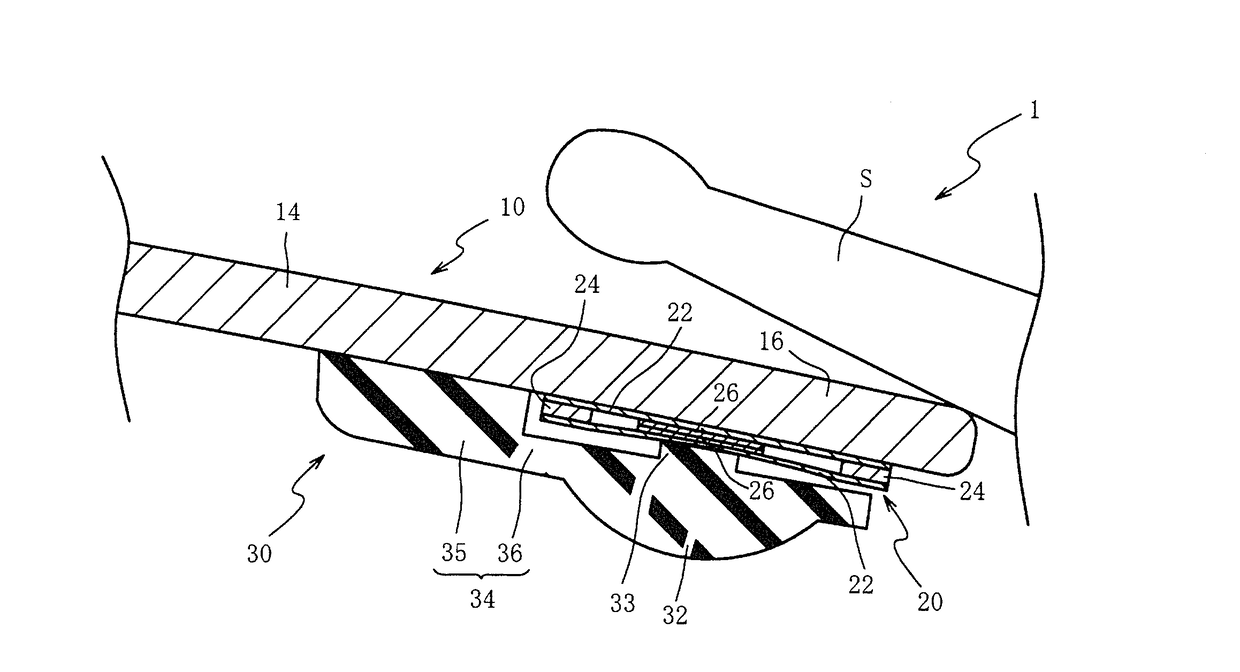
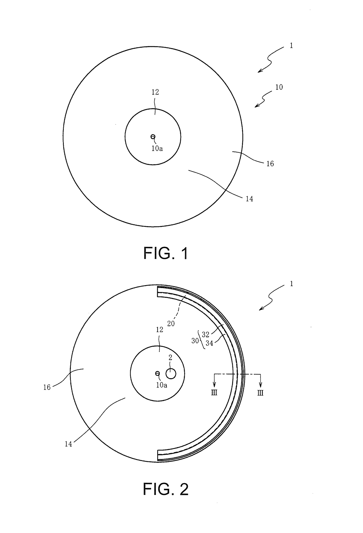
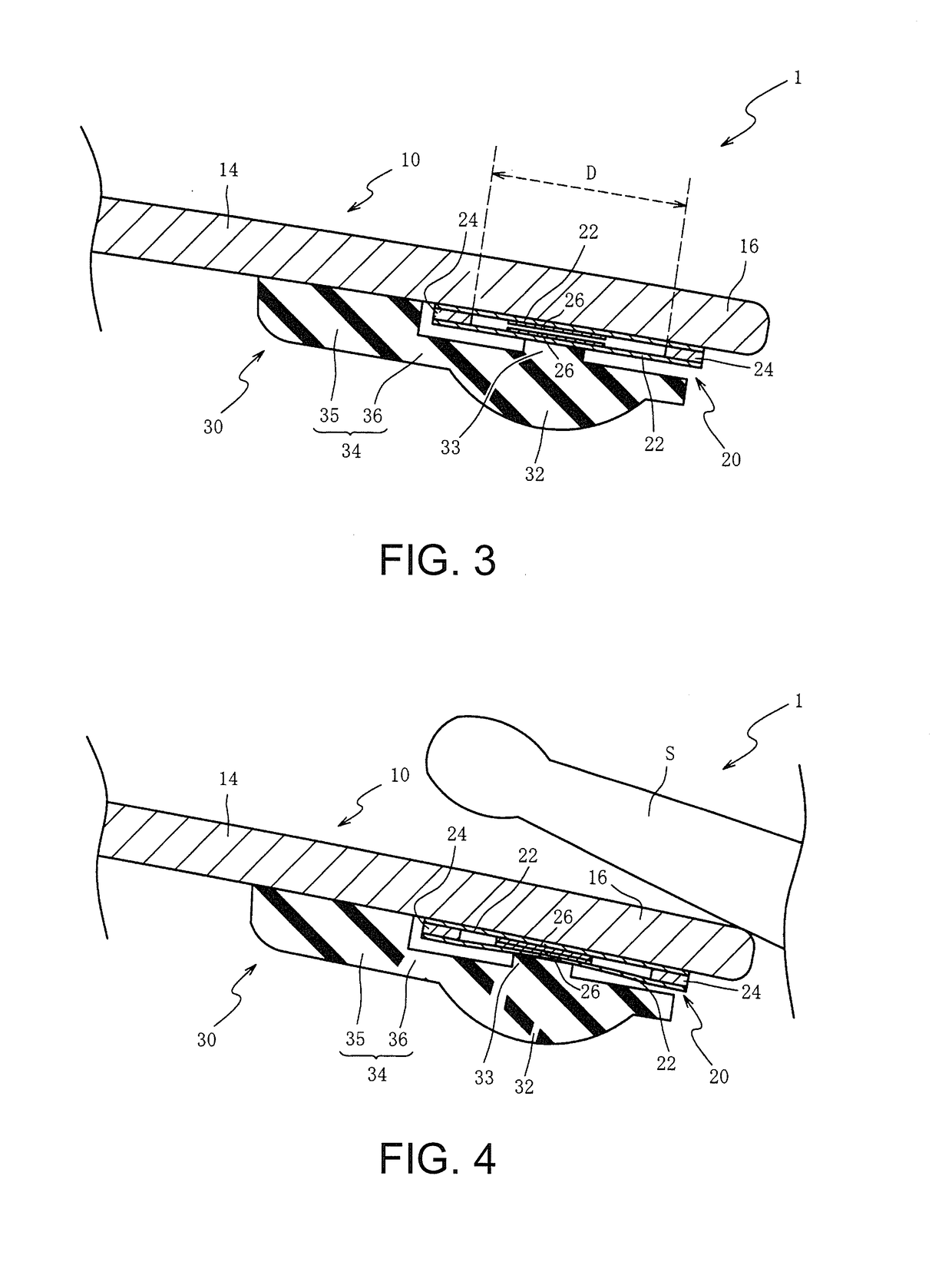
[0099]Next, the second embodiment is explained with reference to FIGS. 12 to 17. In the first embodiment, the weight portion 32 is fixed to the pad 10 through the connection portion 34. Furthermore, the sound source device 40 (struck position detector 40a) includes the ring buffer 43a. In contrast, in the second embodiment, the weight portion 32 is adhered to the pressure sensor 20. Furthermore, the sound source device 40 (struck position detector 40a) includes, in place of the ring buffer 43a, a pressure sensor counter 63b. Moreover, the same parts as those in the first embodiment are denoted with the same reference numerals, and descriptions thereof are omitted in the following description.

[0100]First, a weight portion 51 (weight member) of an electronic percussion instrument 50 is explained with reference to FIG. 12 and FIG. 13. FIG. 12 is a bottom view of the electronic percussion instrument 50 according to the second embodiment. FIG. 13 is a cutaway end view of the electronic p...

Example

[0125]Next, the third embodiment is explained with reference to FIG. 18. In the second embodiment, the weight portion 51 is continuously provided in the circumferential direction of the edge portion 16. In contrast, in the third embodiment, a weight portion 71 is intermittently provided in the circumferential direction of the edge portion 16. Moreover, the same parts as those in the first and the second embodiments are denoted with the same reference numerals, and descriptions thereof are omitted in the following description. FIG. 18 is a bottom view of an electronic percussion instrument 70 according to the third embodiment. As shown in FIG. 18, the electronic percussion instrument 70 includes the circular plate-like pad 10, the vibration sensor 2, the pressure sensor 20, and the weight portion 71 (weight member) that presses the pressure sensor 20.

[0126]The weight portion 71 is made of rubber having a hardness set to 70 degrees, and is a member semicircular in cross section, inter...

Example

[0129]Next, the fourth embodiment is explained with reference to FIG. 19. In the first embodiment, the connection portion 34 that is fixed to the pad 10 at the position closer to the bell portion 12 than the pressure sensor 20 is connected to the weight portion 32. In contrast, in the fourth embodiment, in addition to a first connection portion 82a, a second connection portion 82b is also connected to the weight portion 32. Herein, the first connection portion 82a is fixed to the pad 10 at a position closer to the bell portion 12 than the pressure sensor 20. On the other hand, the second connection portion 82b is fixed to the pad 10 at a position closer to the outer circumferential end of the pad 10 than the pressure sensor 20. Moreover, the same parts as those in the first embodiment are denoted with the same reference numerals, and descriptions thereof are omitted in the following description. FIG. 19 is a cutaway end view of an electronic percussion instrument 80 according to the...


PUM


Abstract

The disclosed electronic percussion instrument includes a plate-like pad that has a front surface to be struck, a sheet-like pressure sensor that is provided on a back surface of an outer circumferential end portion of the pad and that detects a pressure change, and a weight portion that contacts a front surface of the pressure sensor, wherein, due to striking on the front surface of the pad, an inertial force from the front surface of the pressure sensor toward a back surface of the pad acts on the weight portion, and the weight portion presses the pressure sensor.

Description

CROSS-REFERENCE TO RELATED APPLICATION[0001]This application claims the priority benefit of Japanese patent application no. 2015-209156, filed on Oct. 23, 2015. The entirety of the above-mentioned patent application is hereby incorporated by reference herein and made a part of this specification.BACKGROUND OF THE INVENTION[0002]Field of the Invention[0003]The invention relates to an electronic percussion instrument and a struck position detector, particularly to an electronic percussion instrument and a struck position detector capable of improving detection accuracy for a strike.[0004]Description of Related Art[0005]In an electronic percussion instrument such as an electronic cymbal or an electronic hi-hat cymbal, a technique is known of detecting a position struck by a stick or the like by a strike sensor, controlling a sound source based on the struck position, and producing a musical sound. For example, there is disclosed an electronic cymbal including a vibration sensor, a pres...

Claims


Application Information

Patent Timeline
IPC IPC(8): G10H3/14G10H1/22G10D13/02
CPCG10H3/146G10H2230/321G10H1/22G10D13/024G10H1/32G10D13/02G10D13/26G10H3/12
Inventor YOSHINO, KIYOSHITAKASAKI, RYO
Owner ROLAND CORPORATION
Why Eureka
Try Eureka