Firefighter protective garment having varying composite structures to increase dissipation of metabolic heat

a technology of metabolic heat dissipation and composite structure, which is applied in the direction of protective garments, breathing protection, apparel, etc., can solve the problems of not facilitating the dissipation of metabolic heat, achieve enhanced firefighter comfort, facilitate evaporative cooling, and improve evaporative cooling and comfort

Active Publication Date: 2017-05-04
INNOTEX
View PDF2 Cites 0 Cited by
  • Summary
  • Abstract
  • Description
  • Claims
  • Application Information

AI Technical Summary

Benefits of technology

[0027]It is a further object of the present invention to facilitate evaporative cooling and thereby enhance firefighter comfort.
[0028]It is the object of the present invention to improve evaporative cooling and comfort at specific areas inside the garment while maintaining the garment's TPP and THL performance within NFPA 1971 performance requirements.

Problems solved by technology

It does not facilitate the dissipation of metabolic heat via the strategic placement of thinner fabric elements.

Method used


Image

  • Firefighter protective garment having varying composite structures to increase dissipation of metabolic heat
  • Firefighter protective garment having varying composite structures to increase dissipation of metabolic heat
  • Firefighter protective garment having varying composite structures to increase dissipation of metabolic heat

Examples


Embodiment Construction

[0038]In the following description, the same numerical references refer to similar elements. Furthermore, for the sake of simplicity and clarity, namely so as to not unduly burden the figures with several references numbers, not all figures contain references to all the components and features, and references to some components and features may be found in only one figure, and components and features of the present invention illustrated in other figures can be easily inferred therefrom. The embodiments, geometrical configurations, materials mentioned and / or dimensions shown in the figures are optional, and are given for exemplification purposes only.

[0039]Furthermore, although the present invention may be used with various objects, such as firefighter garments, for example, it is understood that it may be used with other types of garments or articles of clothing. For this reason, expressions such as “garments”, etc. as used herein should not be taken as to limit the scope of the pre...


PUM


Abstract

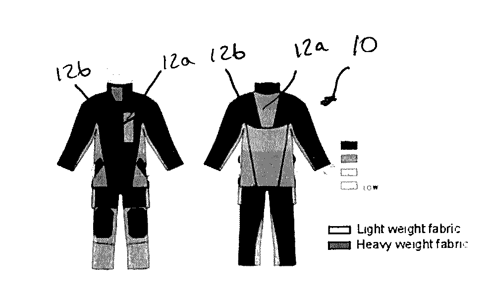
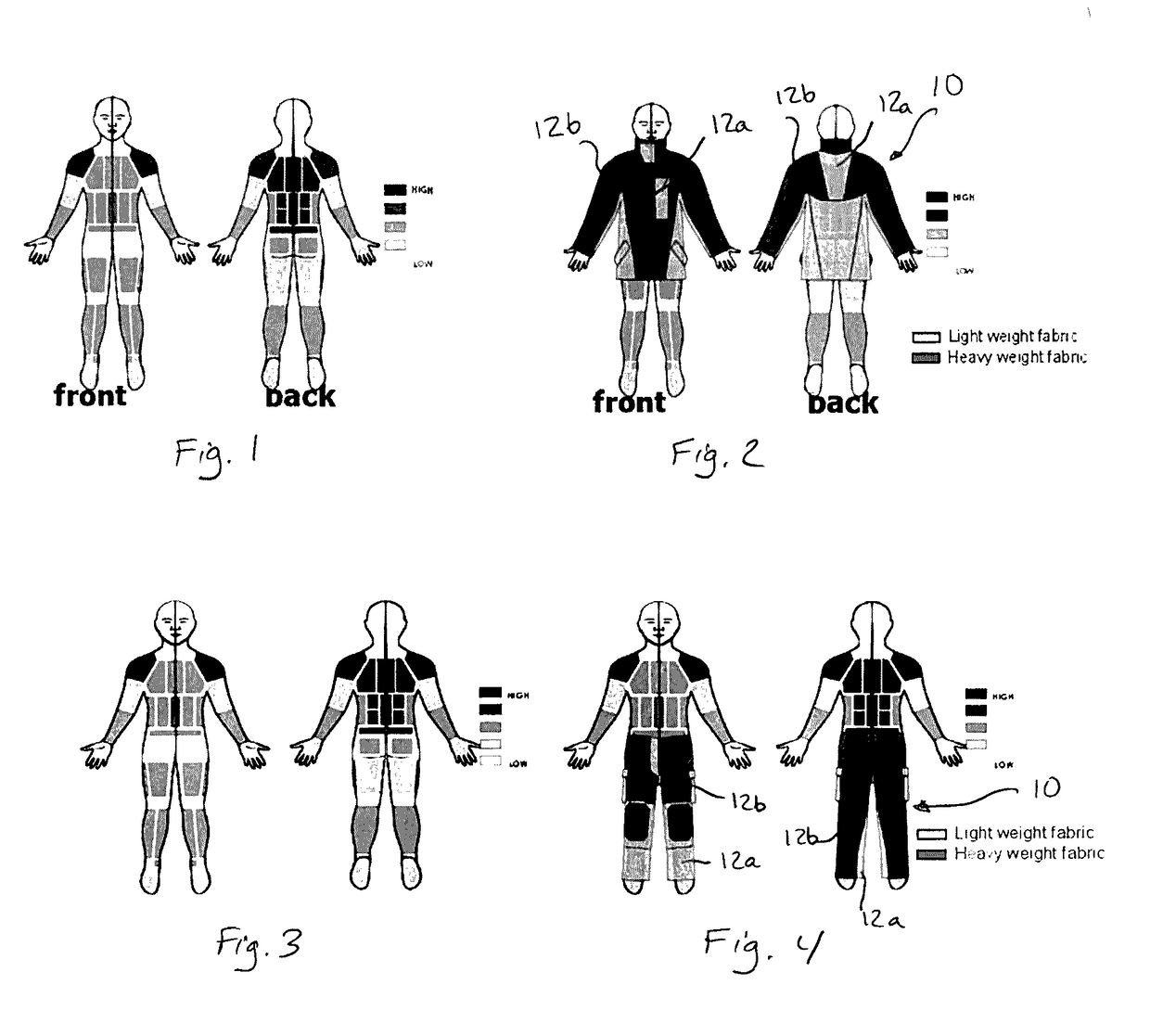
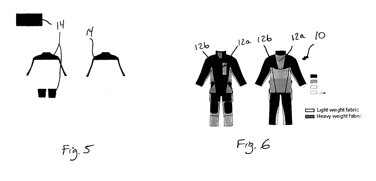
A firefighter's protective garment including an outer shell, moisture barrier and thermal barrier in which the composite structure varies according to the sweating cartography of the human body and in so doing enhances the evacuation of metabolic heat.

Description

FIELD OF THE INVENTION[0001]The present invention generally relates to the design and construction of a firefighter protective garment. More particularly, the present invention is concerned with using lighter weight and / or thinner materials in those areas of the garment that cover those areas of the human body having the highest propensity for sweating.BACKGROUND OF THE INVENTION[0002]A firefighter protective garment is usually a coat or a pant consisting of three or more functional layers of fire-resistant materials. The various layers are normally but not limited to the following:[0003]the outer shell which provides protection against puncture, cuts, abrasion, and heat;[0004]the moisture barrier—consisting usually of a woven or non-woven substrate to which a fire resistant semi-permeable polymer is coated or laminated—which provides resistance to penetration by liquids and blood-borne pathogens while permitting the transmission of perspiration away from the body of the firefighter...

Claims


Application Information

Patent Timeline
Patent Type & Authority Applications(United States)
IPC IPC(8): A62B17/00A41D31/00
CPCA62B17/003A41D31/0027A62B17/005A41D31/085
Inventor BARBEAU, CLAUDEST-ARNEAULT, ERIC
Owner INNOTEX
Why Eureka
Try Eureka