Solid state disk

Inactive Publication Date: 2017-05-04
ALSON TECH LTD
View PDF4 Cites 0 Cited by
  • Summary
  • Abstract
  • Description
  • Claims
  • Application Information

AI Technical Summary

Benefits of technology

[0007]The major object of the present invention is to provide a solid state disk which has a light-emitting portion disposed on another board. When the light-

Problems solved by technology

The cost of replacemen

Method used


Image

  • Solid state disk
  • Solid state disk
  • Solid state disk

Examples


Embodiment Construction

[0019]The present invention will be clearer from the following description when viewed together with the accompanying drawings, which show, for purpose of illustrations only, the preferred embodiment in accordance with the present invention.

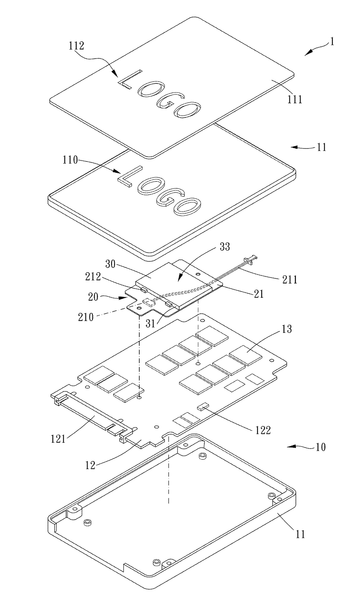
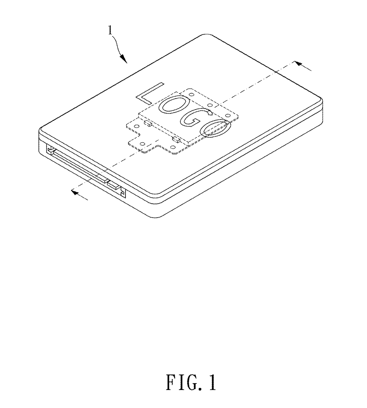
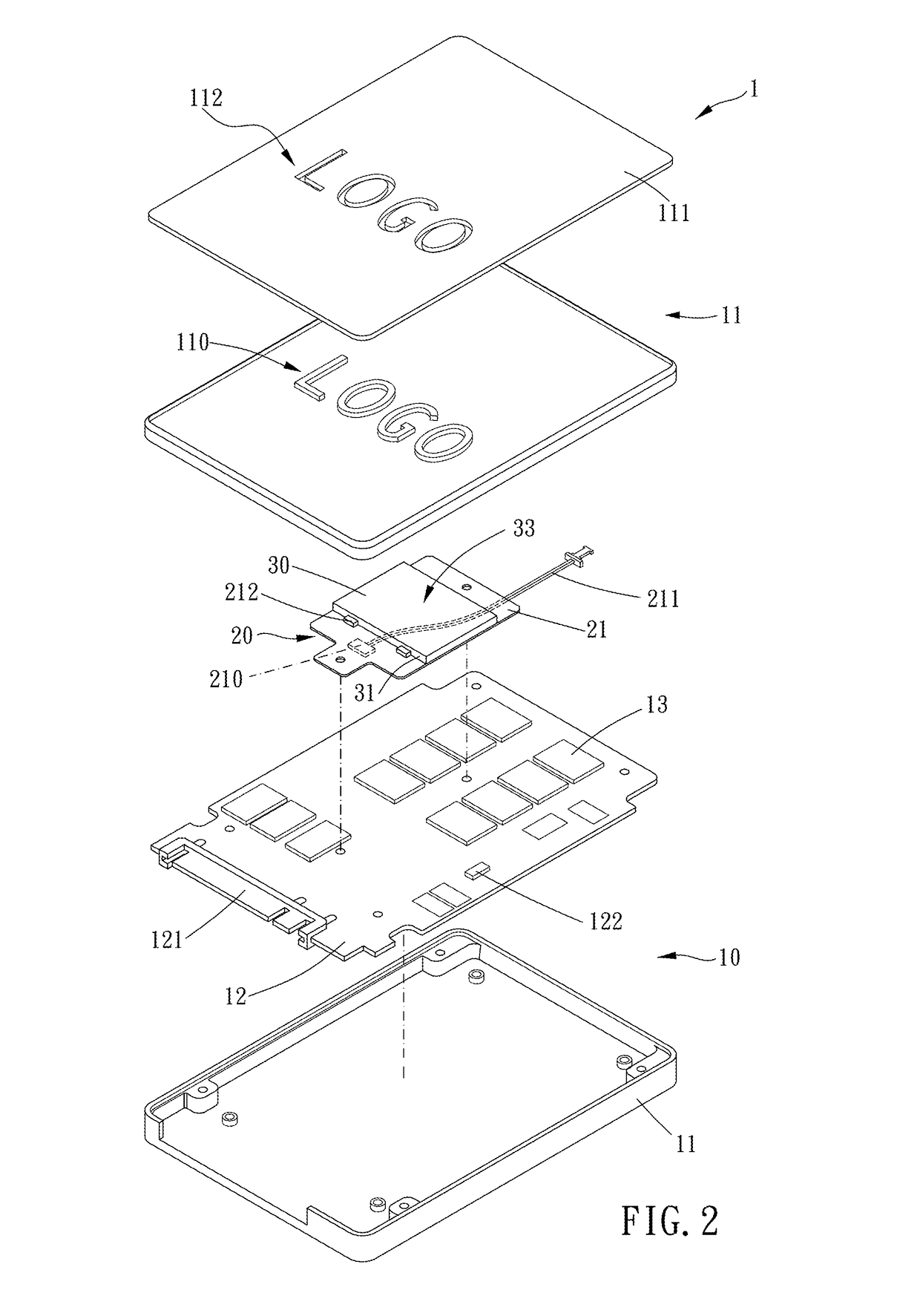
[0020]Please refer to FIGS. 1 to 4 for a preferred embodiment of a solid state disk 1 of the present invention. The solid state disk 1 includes a main body 10, a light-emitting module 20 and a light-guiding portion 30.

[0021]The main body 10 includes a shell portion 11, a substrate 12 disposed in the shell portion 11 and a memory module 13 disposed on the substrate 12. The substrate 12 further has a transmit port 121 electrically connected with the memory modulel3. More specifically, the transmit port 121 is able to transmit not only electric power but data.

[0022]The light-emitting module 20 has a board 21 disposed on the main body 10 and a light-emitting portion 212 disposed on the board 21. Furthermore, the board 21 may be disposed on at least o...


PUM


Abstract

A solid state disk is provided, including: a main body, a light-emitting module and a light-guiding portion. The main body includes a shell portion, a substrate disposed in the shell portion and a memory module disposed on the substrate. The substrate further has a transmit port electrically connected with the memory module. The light-emitting module has a board disposed on the main body and a light-emitting portion disposed on the board. The light-guiding portion is disposed corresponding to the light-emitting portion. At least partial light from the light-emitting portion is transmitted outside the solid state disk through the light-guiding portion.

Description

BACKGROUND OF THE INVENTION[0001]Field of the Invention[0002]The present invention relates to a solid state disk (SSD).[0003]Description of the Prior Art[0004]A conventional solid state disk as disclosed in TWM508102 has a substrate, a memory module, at least one light-emitting portion and at least one light-guiding portion. The substrate further has a transmit port. The memory module is disposed on the substrate. The memory module is electrically connected with the light-emitting portion. The at least one light-guiding portion at least partially covers the at least one light-emitting portion.[0005]However, in actual practice, the light-emitting portion, the substrate and the memory module are connected together. Therefore, if the light-emitting portion is broken, the substrate and the memory module both must be replaced. The cost of replacement is considerably high.[0006]The present invention has arisen to mitigate and / or obviate the afore-described disadvantages.SUMMARY OF THE INV...

Claims


Application Information

Patent Timeline
IPC IPC(8): G06F13/40F21V8/00
CPCG02B6/0043G06F13/4081G02B6/0038G02B6/0095
Inventor CHENG, WEI-DICHENG, HAN-HUNG
Owner ALSON TECH LTD
Why Eureka
Try Eureka