Temperature measuring device and chemical vapor deposition equipment

A technology of temperature measuring device and temperature measuring element, which is applied in the direction of measuring device, gaseous chemical plating, thermometer, etc., can solve the problems of affecting the vapor deposition process and yield, inaccurate temperature measurement results, and short life of temperature measuring elements, etc. Improve the effect of anti-self-weight, not easy to bend, and low cost of preparation and replacement

Pending Publication Date: 2022-07-29
SUZHOU SICREAT NANOTECH CO LTD
View PDF9 Cites 0 Cited by
  • Summary
  • Abstract
  • Description
  • Claims
  • Application Information

AI Technical Summary

Problems solved by technology

[0009] The purpose of the embodiments of the present application is to provide a temperature measuring device and chemical vapor deposition equipment, which can improve the temperature measurement caused by the large bending of the existing temperature measuring device when it is actually applied to a large-scale chemical vapor deposition setting Inaccurate results, easy to vibrate and affect the vapor deposition process and yield, as well as technical problems such as short life of temperature measuring components and high replacement costs

Method used


Image

  • Temperature measuring device and chemical vapor deposition equipment
  • Temperature measuring device and chemical vapor deposition equipment
  • Temperature measuring device and chemical vapor deposition equipment

Examples


Embodiment 1

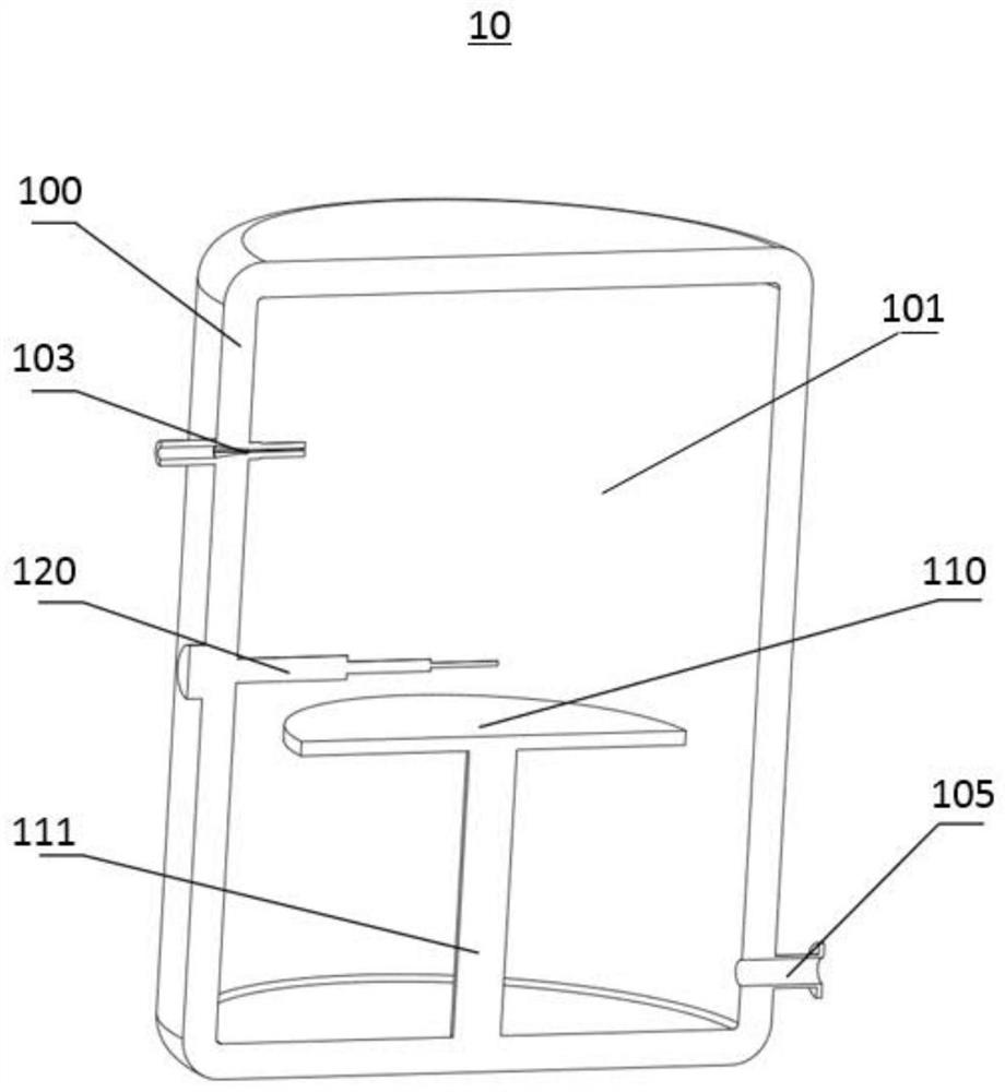
[0052] see figure 1 , a chemical vapor deposition equipment 10 , which mainly includes a furnace body 100 , a stage 110 and a temperature measuring device 120 .

[0053] The furnace body 100 has a furnace cavity 101, and precursors and other reaction gases are reacted and deposited in the furnace cavity 101, wherein the furnace body 100 is provided with an air inlet 103 and an exhaust port 105 communicating with the furnace cavity 101, and the air inlet 103 is used for The mixed gas containing the precursors and other reaction gases is transported into the furnace cavity 101, and the exhaust port 105 is used to discharge the mixed substances of the unreacted precursors and gases, reaction products and other by-products from the furnace cavity 101, so that After new precursors and other reaction gases enter the furnace cavity 101 , the position of the exhaust port 105 is lower than the horizontal plane where the intake port 103 is located.

[0054] Generally, the cross section...

Embodiment 2

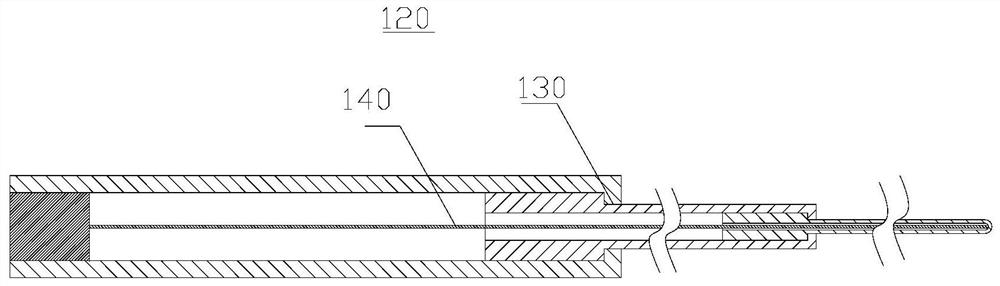
[0087] see figure 2 as well as image 3 , the temperature measurement device 120 provided in this embodiment includes a multi-level structure 130 and a temperature measurement element 140 installed in the multi-level structure 130 .

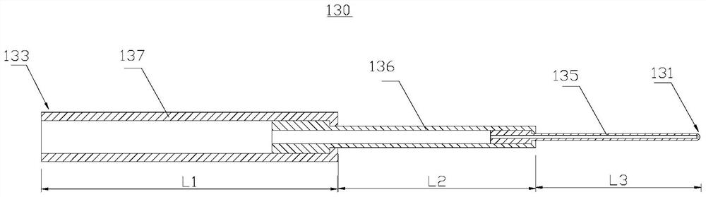
[0088] The multi-stage structure 130 is a three-stage sleeve, and the multi-stage structure 130 has a first sleeve 135 , a second sleeve 136 and a third sleeve 137 which are detachably connected along the axial direction from the first end 131 to the second end 133 . The inner diameter of the first sleeve 135 is 4mm, the wall thickness is 2mm, the length is 200mm, and the material is graphite; the inner diameter of the second sleeve 136 is 16mm, the wall thickness is 5mm, the length is 240mm, and the material is graphite; the third sleeve 137 The inner diameter is 40mm, the wall thickness is 10mm, the length is 360mm, and the material is graphite.

[0089] The temperature measuring element 140 is a thermocouple, and the temperature measuring e...

Embodiment 3

[0091] see figure 2 as well as image 3 , the temperature measurement device 120 provided in this embodiment includes a multi-level structure 130 and a temperature measurement element 140 installed in the multi-level structure 130 .

[0092] The multi-stage structure 130 is a three-stage sleeve, and the multi-stage structure 130 has a first sleeve 135 , a second sleeve 136 and a third sleeve 137 which are detachably connected along the axial direction from the first end 131 to the second end 133 . The inner diameter of the first sleeve 135 is 4mm, the wall thickness is 2mm, the length is 200mm, and the material is silicon carbide; the inner diameter of the second sleeve 136 is 16mm, the wall thickness is 5mm, the length is 240mm, and the material is graphite; the third sleeve The inner diameter of 137 is 40mm, the wall thickness is 10mm, the length is 360mm, and the material is graphite.

[0093] The temperature measuring element 140 is a thermocouple, and the temperature m...


PUM

PropertyMeasurementUnit
thicknessaaaaaaaaaa
thicknessaaaaaaaaaa
thicknessaaaaaaaaaa

Abstract

The invention provides a temperature measuring device and chemical vapor deposition equipment, and relates to the technical field of temperature measurement. The temperature measuring device comprises a horizontally arranged multi-stage structure and a temperature measuring element. The multi-stage structure is provided with multi-stage sleeves detachably connected in the axial direction of the multi-stage structure, the multi-stage structure is provided with a first end and a second end which are opposite in the axial direction of the multi-stage structure, the first end is a closed end, and in any two adjacent stages of sleeves, the inner diameter of the sleeve close to the first end is smaller than that of the sleeve close to the second end. The length of the sleeve close to the first end is smaller than that of the sleeve close to the second end; the axial length of the multi-stage structure is larger than or equal to 800 mm, the wall thickness of the portion, located at the first end, of the sleeve is smaller than 3 mm, and the temperature measuring element is detachably installed in the multi-stage structure and used for measuring the temperature of the end of the first end. According to the multi-stage structure, the self-weight resistance of the temperature measuring device can be improved, so that when the temperature measuring device is applied to the chemical vapor deposition equipment for temperature measurement, the deviation degree of the first end in the gravity direction can be slowed down, and the temperature measuring accuracy is improved.

Description

technical field [0001] The present application relates to the technical field of temperature measurement, and in particular, to a temperature measurement device and chemical vapor deposition equipment. Background technique [0002] At present, thermocouples and infrared thermometers are mainly used to measure the deposition temperature in chemical vapor deposition equipment. However, for chemical vapor deposition systems of some materials, such as silicon nitride materials, etc., there are severe conditions such as high deposition temperature, long deposition time, and deposition film thickness. [0003] Usually chemical vapor deposition equipment directly uses infrared thermometer or thermocouple as the temperature measuring element for temperature measurement. [0004] Among them, the infrared thermometer measures the temperature by receiving the infrared energy on the surface of the material, but this method is very sensitive to the surface material and distance of the o...

Claims


Application Information

Patent Timeline
Patent Type & Authority Applications(China)
IPC IPC(8): G01K13/00G01K1/08G01K1/10G01J5/02G01J5/04C23C16/52
CPCG01K13/00G01K1/08G01K1/10G01J5/02G01J5/048C23C16/52
Inventor 不公告发明人
Owner SUZHOU SICREAT NANOTECH CO LTD
Why Eureka
Try Eureka