Modular water heater
A technology for water heaters and hot water, applied in heat storage heaters, fluid heaters, lighting and heating equipment, etc., can solve the problems of increasing fault points, lack of creativity, and increasing costs, achieve low replacement costs, solve after-sales maintenance, The effect of saving social resources
- Summary
- Abstract
- Description
- Claims
- Application Information
AI Technical Summary
Problems solved by technology
Method used
Image

Examples
Embodiment 1
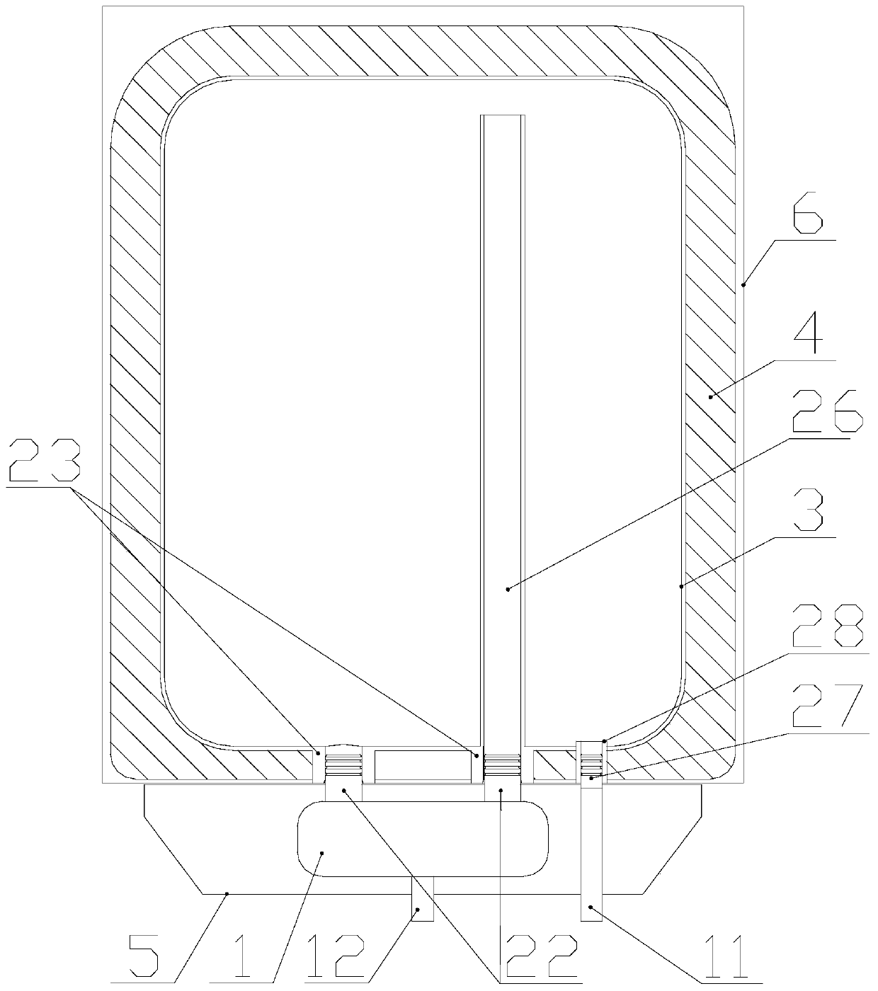
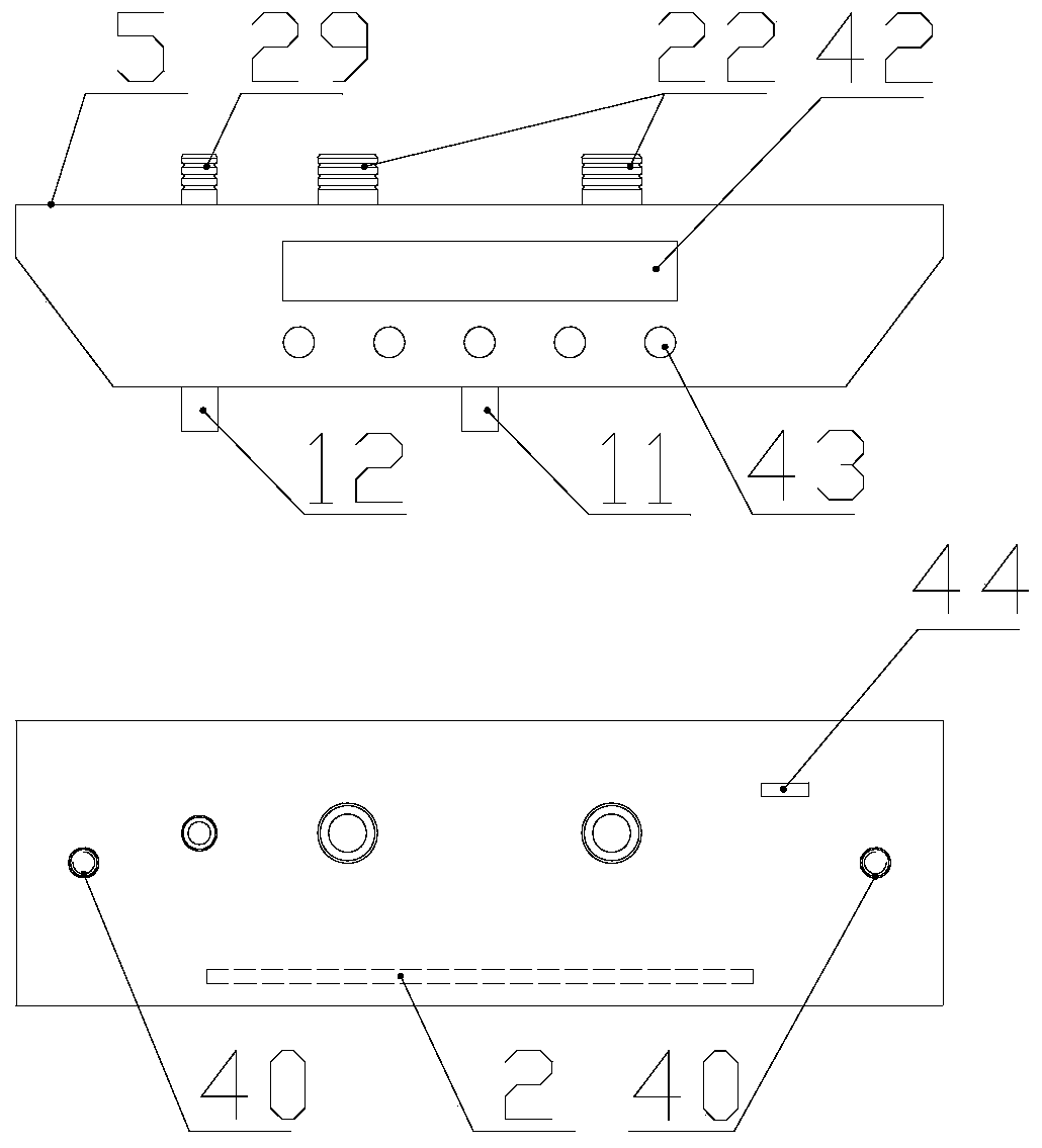
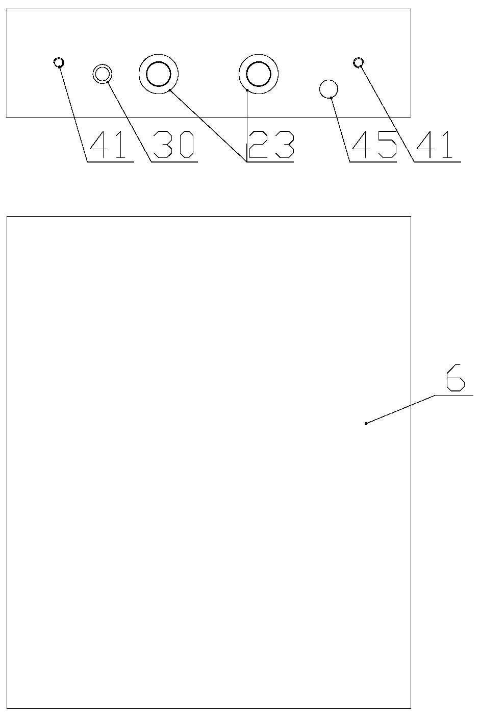
[0043] Figure 1 to Figure 5 It is a structural schematic diagram of a water heater according to the first embodiment of the present invention, and the first embodiment is a modular water heater solution specially for natural convection. figure 2 is the schematic diagram of the heating module, image 3 is the schematic diagram of the heat storage module, figure 1 , 4 , 5 is a structural schematic diagram of the combination of the heating module and the heat storage module.
[0044] Such as figure 1 As shown, the heating module is assembled on the bottom of the heat storage module, the two convection ports 22 on the heat storage module are inserted into the convection port 2 23 of the heat storage module, and the cold water port 1 27 on the heat storage module is inserted into the cold water port of the heat storage module Two 28 in. The two convection ports one 22 are connected to the shell of the heating unit 1 and can be fixed by threaded connection or welding, and the...
Embodiment 2
[0050] Figure 6 , Figure 7 , Figure 8 It is a schematic structural diagram of Embodiment 2. This embodiment is a modular water heater solution that uses heat exchange technology to solve scale problems, tank corrosion and life problems. At the same time, this embodiment also uses natural convection heating.
[0051] Such as Figure 6 As shown, a primary heat exchanger 10 is installed in the heat storage module, and the water inlet end of the primary heat exchanger is provided with a cold water interface 228. The primary heat exchanger in the figure is a tubular heat exchanger, which can also be used as required The heat exchanger structure such as tube-fin type is adopted, and a more suitable heat exchanger structure is selected based on cost and efficiency. The water outlet end of the primary heat exchanger 10 is connected to the heat exchanger interface 2 39 . The cold water interface 2 28 and the heat exchanger interface 2 39 can be connected to the heat exchanger by...
Embodiment 3
[0056] Figure 9 to Figure 13 It is a part of the forced convection modular water heater scheme. The difference from natural convection is that the pump 15 is added. The advantage of forced convection is that the installation position of the heating module does not have to be limited to the bottom of the heat storage module, such as Figure 13 It is installed on the top, which is very useful in some occasions. For example, the small kitchen treasure, because it is placed under the faucet, the interface can be connected at the top; beautiful. In addition, forced convection is more conducive to the control of convection intensity and improves the working conditions of the heater. For example, in natural convection, the convection speed is slow, the surface temperature of the heater is high, and there are dead water areas with insufficient convection, resulting in local high temperature. The natural convection interface requires a sufficiently large caliber, and the location, si...
PUM
 Abstract
Description
Claims
Application Information