Encryption apparatus, storage system, decryption apparatus, encryption method, decryption method, and computer readable medium
- Summary
- Abstract
- Description
- Claims
- Application Information
AI Technical Summary
Benefits of technology
Problems solved by technology
Method used
Image
Examples
first embodiment
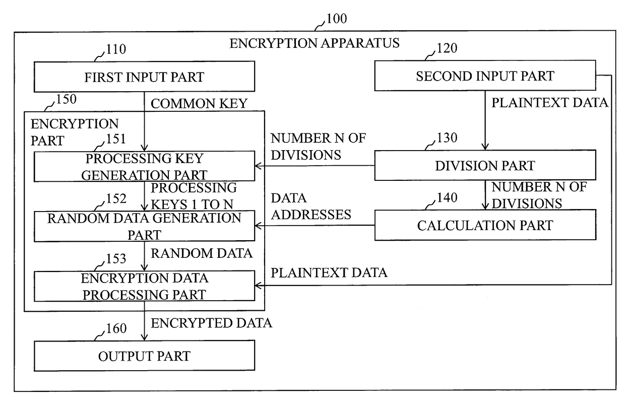
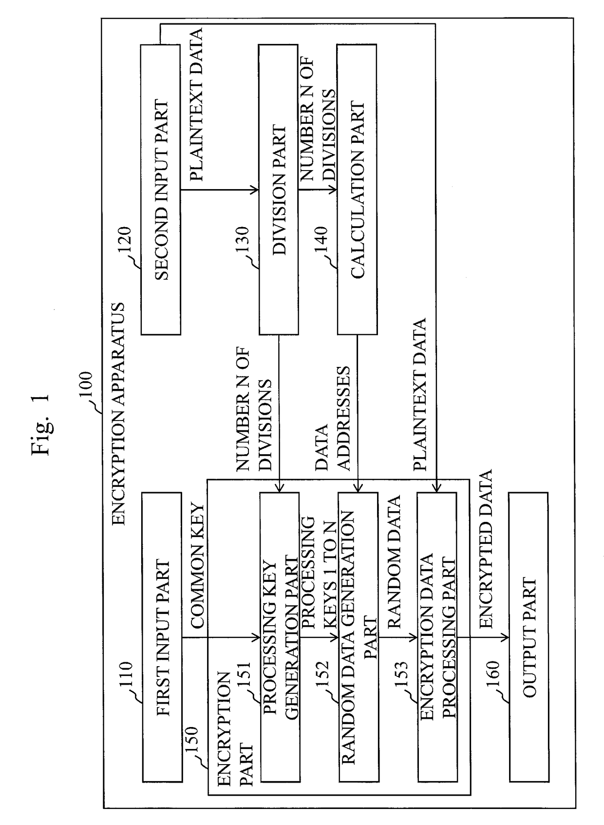
[0030]FIG. 1 is a block diagram illustrating a configuration of an encryption apparatus 100 according to the present embodiment.
[0031]The encryption apparatus 100 encrypts plaintext data (also referred to as “processing data”) by means of a block cipher F.
[0032]Referring to FIG. 1, the encryption apparatus 100 includes a first input part 110, a second input part 120, a division part 130, a calculation part 140, an encryption part 150, and an output part 160.
[0033]The first input part 110 has an interface function to receive from the outside a common key (also referred to as a “secret key”) to be used for the block cipher F. The first input part 110 holds the common key received from the outside in a memory. The first input part 110 transmits the common key held in the memory to the encryption part 150.
[0034]As just described, the first input part 110 inputs the common key to the encryption part 150.
[0035]The second input part 120 has an interface function to receive from the outside...
second embodiment
[0075]FIG. 8 is a block diagram illustrating a configuration of a decryption apparatus 200 according to the present embodiment.
[0076]The decryption apparatus 200 decrypts the encrypted data by means of a block cipher F. The block cipher F is the same as that of the first embodiment.
[0077]Referring to FIG. 8, the decryption apparatus 200 includes a first input part 210, a second input part 220, a division part 230, a calculation part 240, a decryption part 250, and an output part 260.
[0078]The first input part 210, the second input part 220, the division part 230, the calculation part 240, the decryption part 250, and the output part 260 respectively have functions corresponding to the first input part 110, the second input part 120, the division part 130, the calculation part 140, the encryption part 150, and the output part 160 of the encryption apparatus 100 according to the first embodiment.
[0079]The first input part 210 inputs a common key to the decryption part 250.
[0080]The se...
third embodiment
[0090]FIG. 9 is a block diagram illustrating a configuration of a storage system 300 according to the present embodiment.
[0091]Referring to FIG. 9, the storage system 300 includes the same encryption apparatus 100 as the first embodiment and the same decryption apparatus 200 as the second embodiment. Further, the storage system 300 includes a tamper resistant device 310, a control device 320, and a storage medium 330.
[0092]The tamper resistant device 310 stores a common key. The common key is the same as those in the first and second embodiments.
[0093]When receiving from the outside a request to write data to the storage medium 330, the control device 320 transmits to the encryption apparatus 100 an instruction to write the data to the storage medium 330, and also transmits the common key from the tamper resistant device 310 to the encryption apparatus 100. Further, when receiving from the outside a request to read data from a specific address of the storage medium 330, the control ...
PUM
 Abstract
Description
Claims
Application Information
 - R&D
- Intellectual Property
- Life Sciences
- Materials
- Tech Scout
- Unparalleled Data Quality
- Higher Quality Content
- 60% Fewer Hallucinations
Browse by: Latest US Patents, China's latest patents, Technical Efficacy Thesaurus, Application Domain, Technology Topic, Popular Technical Reports.
© 2025 PatSnap. All rights reserved.Legal|Privacy policy|Modern Slavery Act Transparency Statement|Sitemap|About US| Contact US: help@patsnap.com


