Single access surgical robotic devices and systems, and methods of configuring single access surgical robotic devices and systems

a single-access, surgical robotic technology, applied in the field of single-access surgical robotic devices and systems, can solve the problems of surgical robotic devices, surgical robotic arms, and oftentimes encounter difficulties during operation, and the instrument attached to the end of the surgical robotic arm is typically limited to access

Active Publication Date: 2017-05-11
IEMIS (HK) LTD
View PDF13 Cites 3 Cited by
  • Summary
  • Abstract
  • Description
  • Claims
  • Application Information

AI Technical Summary

Benefits of technology

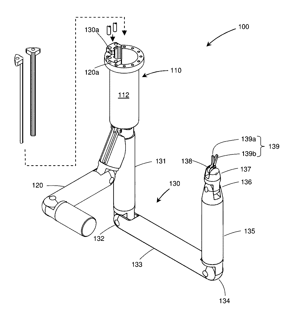
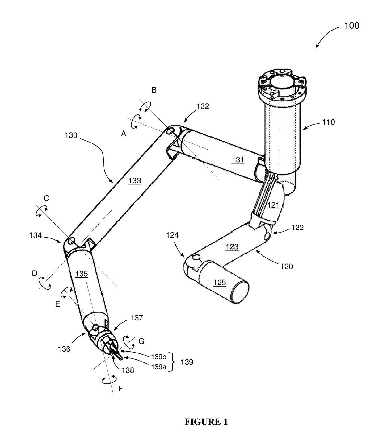
[0011]In another exemplary embodiment, a method for configuring a surgical device for performing a surgical action in the abdominal cavity of a patient is described in the present disclosure. The method comprises providing an external anchor and a port assembly having an outer body member and an inner body member. The method further comprises providing a camera arm assembly, the camera arm assembly having a serial arrangement including a plurality of camera arm segments, a plurality of camera joint portions, and at least one camera attached to one of the camera arm segments. In this regard, each camera joint portion is configurable to provide an attached camera arm segment with at least one degree of freedom. The method further comprises providing a plurality of instrument arm assemblies, each instrument arm assembly having a serial arrangement including a plurality of arm segments, a plurality of joint portions, and at least one end instrument attached to one of the arm segments at a distal end. In this regard, each joint portion is configurable to provide an attached arm segment with at least two degrees of freedom. The method further comprises positioning the outer body member in at least a portion of an opening of a patient in one of a plurality of positions using the external anchor. The method further comprises inserting the camera arm assembly into the abdominal cavity of the patient via a first port of the outer body member, and dynamically configuring one or more of the camera joint portions in such a way as to prevent a portion of the camera arm assembly from contacting with the inner wall of the abdominal cavity of the patient and to provide a clear passageway into the abdominal cavity of the patient via the first port. The method further comprises attaching the camera arm assembly to the outer body member. The method further comprises inserting one of the instrument arm assemblies into the abdominal cavity of the patient via the first port of the outer body member, and dynamically configuring one or more of the joint portions in such a way as to prevent a portion of the instrument arm assembly from contacting with the inner wall of the abdominal cavity of the patient and to provide a clear passageway into the abdominal cavity of the patient via the first port. The method further comprises attaching the inserted instrument arm assembly to the outer body member. The method further comprises repeating the inserting and dynamic configuring of the instrument arm assembly for one or more other instrument arm assemblies. The method further comprises securing the inner body member into the first port of the outer body member to form a second port. The method further comprises inserting one or more surgical equipment into the second port.

Problems solved by technology

As another example, it is recognized in the present disclosure that surgical robotic devices, including surgical robotic arms, oftentimes encounter difficulties during surgical procedures due to insufficient anchoring and / or reactive forces to stabilize against forces that are desired and / or necessary to be applied during surgical actions.
That is, after the surgical robotic arm is inserted in the abdominal cavity of the patient and ready to perform a surgical action, the instrument attached to the end of the surgical robotic arm is typically limited to access only certain parts, areas, and quadrants of the abdominal cavity of the patient.

Method used


Image

  • Single access surgical robotic devices and systems, and methods of configuring single access surgical robotic devices and systems
  • Single access surgical robotic devices and systems, and methods of configuring single access surgical robotic devices and systems
  • Single access surgical robotic devices and systems, and methods of configuring single access surgical robotic devices and systems

Examples


Embodiment Construction

[0057]Example embodiments will now be described with reference to the accompanying drawings, which form a part of the present disclosure, and which illustrate example embodiments which may be practiced. As used in the present disclosure and the appended claims, the terms “example embodiment,”“exemplary embodiment,” and “present embodiment” do not necessarily refer to a single embodiment, although they may, and various example embodiments may be readily combined and / or interchanged without departing from the scope or spirit of example embodiments. Furthermore, the terminology as used in the present disclosure and the appended claims is for the purpose of describing example embodiments only and is not intended to be limitations. In this respect, as used in the present disclosure and the appended claims, the term “in” may include “in” and “on,” and the terms “a,”“an” and “the” may include singular and plural references. Furthermore, as used in the present disclosure and the appended cl...


PUM


Abstract

Example embodiments relate to a device comprising a port assembly, instrument arm assembly, and camera arm assembly. The port assembly includes an outer and inner body. The outer body includes a first access port, first end, second end, and anchoring portions. The inner body is positionable in the first access port to form a second access port. The instrument arm assembly is configurable in a serial arrangement of arm segments, joint portions, and end instrument. The instrument arm assembly is configurable to attach to an anchoring portion. The camera arm assembly includes a camera, and configurable to attach to an anchoring portion. The port assembly is configurable to provide at least one degree of freedom, and configurable to allow insertion of the instrument arm assembly and camera arm assembly into an abdominal cavity. The port assembly is configurable to allow insertion of instruments into the abdominal cavity.

Description

CROSS REFERENCE TO RELATED APPLICATIONS[0001]This is a divisional application of and claims priority to U.S. patent application Ser. No. 14 / 693,207, filed on Apr. 22, 2015 entitled “Single access surgical robotic devices and systems, and methods of configuring single access surgical robotic devices and systems” by Yeung that is a non-provisional of and claims priority to U.S. Provisional Patent Application No. 61 / 982,717, filed on Apr. 22, 2014 entitled “Single access surgical robotic devices, systems, and methods thereof” by Yeung, both of which are hereby incorporated by reference in their entirety.BACKGROUND[0002]The present disclosure relates generally to surgical systems, devices, and methods, and more specifically, relates to systems and devices for use in performing Minimally Invasive Surgical (MIS) procedures, and methods of configuring such surgical systems and devices.[0003]With the advancement of medical science and technology, most conventional open surgical procedures, ...

Claims


Application Information

Patent Timeline
Patent Type & Authority Applications(United States)
IPC IPC(8): A61B34/30A61B1/00A61B90/00A61B17/34A61B34/00
CPCA61B34/30A61B17/00234A61B34/76A61B90/361A61B1/00147A61B2017/00283A61B2017/3445A61B2017/346A61B2034/305A61B90/30A61B2090/3612A61B1/05A61B1/3132A61B34/37A61B17/3423A61B17/3421A61B2090/309Y10S901/02Y10S901/27A61B1/00149A61B1/0016A61B1/00133
Inventor YEUNG, CHUNG-KWONGYUNG, KAI-LEUNGTO, JIMMY TSUN-PING
Owner IEMIS (HK) LTD
Why Eureka
Try Eureka