Seal for medical instrument

a technology for medical instruments and seals, applied in the field of seals for medical instruments, can solve the problems of unintentional leakage of electrical current, septic contamination of laparoscopic devices, and complications, and achieve the effect of reducing the risk of electrical shock and/or contamination

Inactive Publication Date: 2007-02-01
MICROLINE PENTAX
View PDF3 Cites 116 Cited by
  • Summary
  • Abstract
  • Description
  • Claims
  • Application Information

AI Technical Summary

Benefits of technology

[0004] Accordingly, it is a feature of the present invention to mitigate the risk of electrical shock and / or contamination of a tube by fluids, and to provide isolation from electrical shock and / or shorting caused by fluid contact.
[0007] The laparoscopic tube end may also include an interior to receive a yoke of the tip, and an interior threaded portion to threadedly engage with the yoke of the tip. In addition, the gasket may have an outer radius which increases from an uncompressed radius to a maximal radius when the gasket is compressed by the tip against the contact surface of the flange, in which the maximal radius does not exceed an outermost radius of the flange. Further, grease may be disposed on any one or more of the flange, the groove, the engagement portion, the instrument tip or the gasket, and may seal and / or insulate an interior of the tube end from an exterior of the tube end; also, the engagement portion may include threading on an exterior surface of the instrument tip and / or an interior surface of the instrument tip.

Problems solved by technology

However, when a tip is detachably connected to the tube end of a laparoscopic device, complications may occur if fluid breaches the connection and enters the interior of the tip or tube end.
For example, septic contamination may arise in the laparoscopic device and / or electrical current may unintentionally leak therefrom.

Method used


Image

  • Seal for medical instrument
  • Seal for medical instrument
  • Seal for medical instrument

Examples


second embodiment

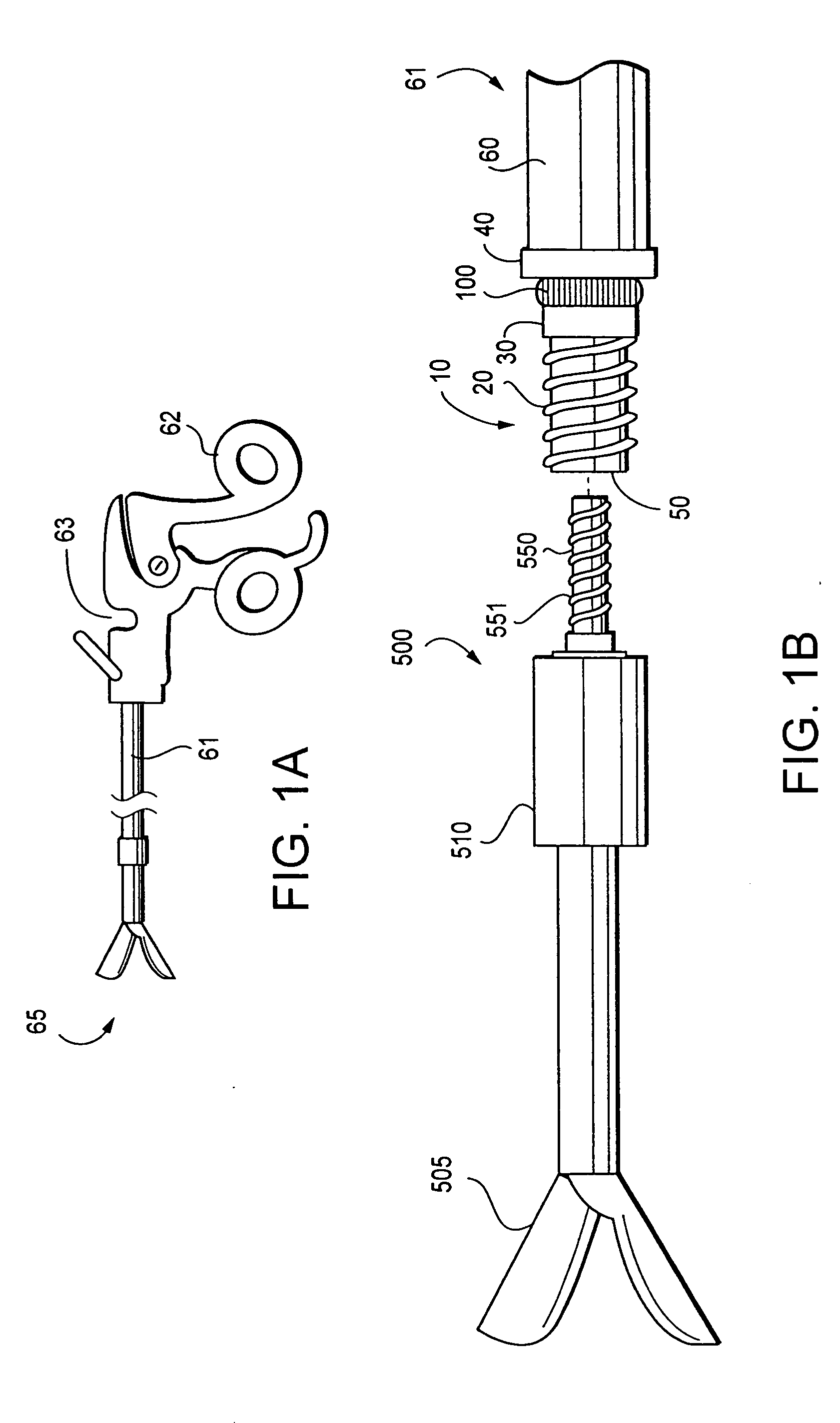
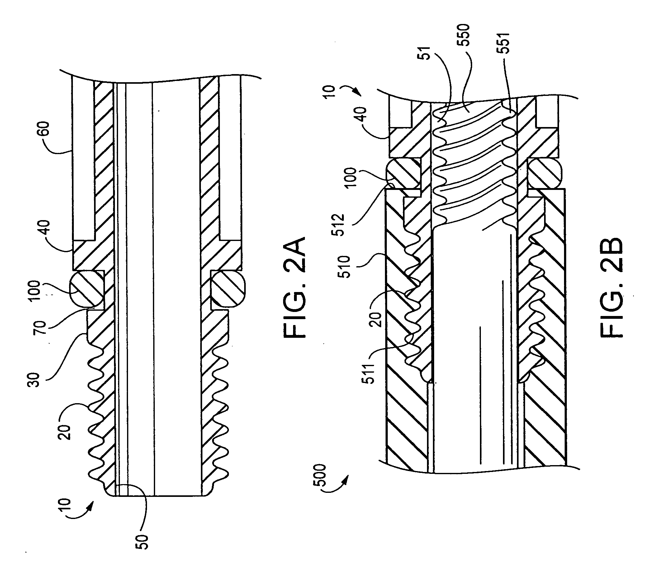
[0028]FIGS. 4, 5A and 5B illustrate the present invention, in which the tip 500. includes a first seal 200 where the back hub 510 contacts an extremity of the tube end 10. Accordingly, as the back hub 510 is tightened against the tube end 10, a seal is created by compression of the elastomeric material of the first seal 200 between the distal tip 21 of the tube end 10 and the compression surface 501 of the back hub 510, for example. Although the first seal 200 is exemplified as attached to the back hub 510 of the tip 500, it may alternatively be attached to the extremity of the tube end 10, for example. Furthermore, the cross-section of the first seal 200 may have any appropriate form, such as square, circular, or any other suitable form.

[0029] As shown in FIG. 5A, the tube end 10 may also include a second seal 110 adjacent to the flange 40 of the laparoscopic tube end 10. According to one aspect of the second embodiment, the second seal 110 may have a cross-sectional diameter or ar...

third embodiment

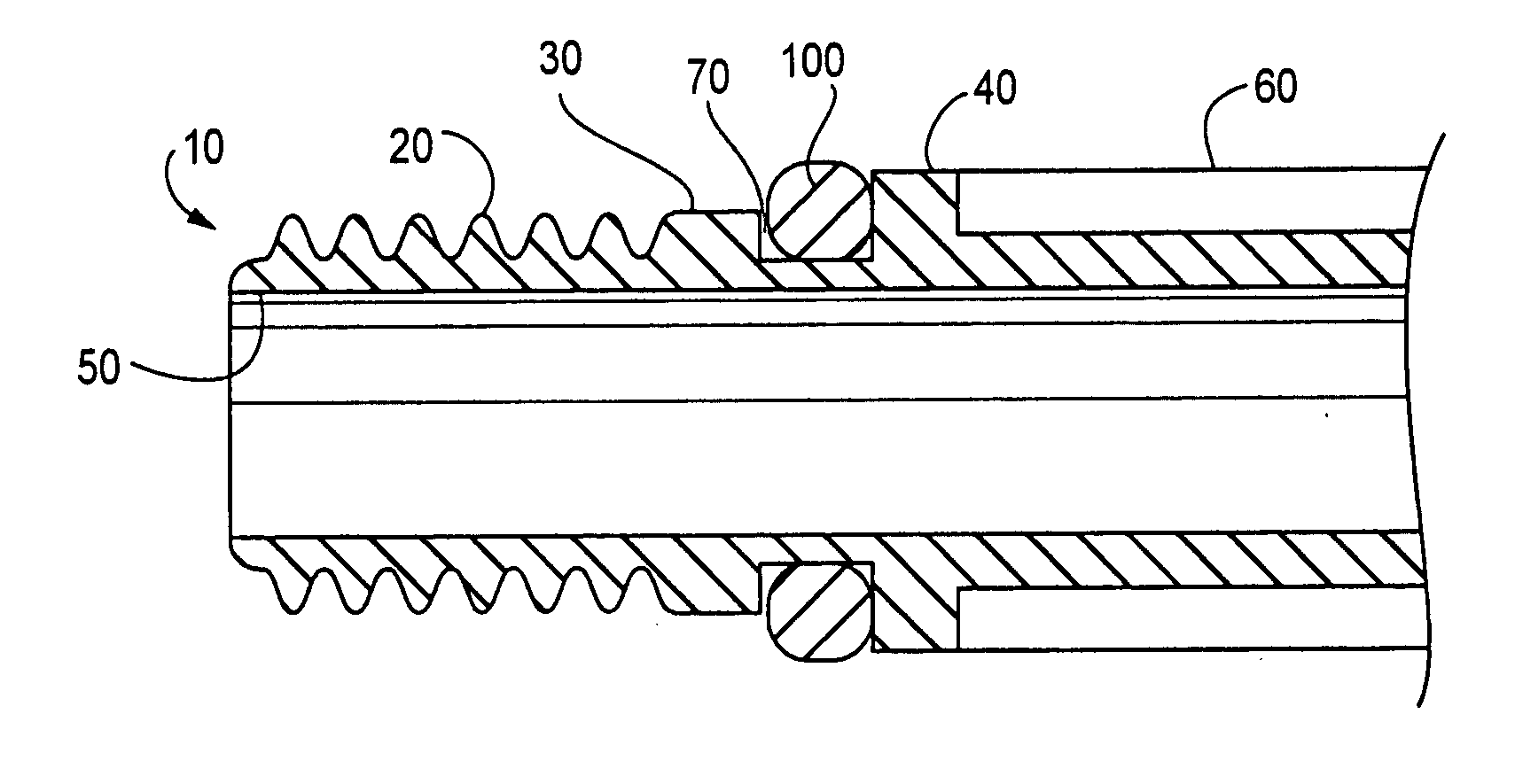
[0031] According to another aspect of the third embodiment, the laparoscopic tube end 11 may include a groove 70 into which a band 700 of heat-shrink material is disposed. The heat-shrink material, which may be formed either entirely or partially of at least one type of fluorinated ethylene propylene (FEP) material, may have a shape and material composition selected so as to generate minimal additional friction during engagement of the tip 500 to the laparoscopic tube end 11 beyond the friction that would otherwise produced by the laparoscopic tube end 11 if the band 700 of heat-shrink material were not included. When the tip 500 is engaged with the laparoscopic tube end 11, the band 700 of heat-shrink material may provide a water-resistant seal, enhancing the fluid-resistant and electrically insulating properties of the laparoscopic device 65.

[0032] In a further aspect of the third embodiment, the interior 50 of the tube end 11 may include a metal interface or adapter 600 made of s...


PUM


Abstract

A laparoscopic tube end for interfacing a tube with a tip may include an attachment portion to attach to the tip, and a tapered flare portion to frictionally abut the tip when the tip is attached to the tube end.

Description

1. FIELD OF THE INVENTION [0001] This invention relates to a medical instrument including an electrosurgical apparatus, such as a laparoscopic tube end used for performing laparoscopic, pelvoscopic, arthroscopic, thoroscopic and / or similar such procedures, and more particularly to an electrosurgical apparatus having a fluid-resistant seal for fluidically isolating and electrically insulating a detachable tip when engaged with a laparoscopic tube end. 2. BACKGROUND OF THE INVENTION [0002] Medical procedures such as laparoscopy and the like, which employ a tip at the end of a tube for insertion into the patient, are beneficial because the incisions necessary to perform them are minimal in size, therefore promoting more rapid recovery and lower costs. For example, a patient who undergoes laparoscopic surgery may typically return to normal activity within a period of a few days to about a week, in contrast to more invasive procedures requiring a relatively larger incision (which may req...

Claims


Application Information

Patent Timeline
Patent Type & Authority Applications(United States)
IPC IPC(8): A61B18/18
CPCA61B17/29A61B2017/2931A61B2017/00473A61B18/085
Inventor THEROUX, MARCEWASCHUK, MICHAELDEGUILLEBON, HENRIALISKI, PETERPELLETIER, DENNISMAZEJKA, BRIAN
Owner MICROLINE PENTAX
Why Eureka
Try Eureka