Laparoscopic instruments and methods utilizing suction

a technology applied in the field of laparoscopic instruments and methods utilizing suction, can solve the problems of increasing the size of the wound to be dilated, increasing the size of the bag, and reducing so as to minimize the cross section of the tissue, reduce the force required to remove the tissue, and minimize the effect of the need for wound dilation

Inactive Publication Date: 2006-02-02
LOGUIDICE MARK
View PDF51 Cites 125 Cited by
  • Summary
  • Abstract
  • Description
  • Claims
  • Application Information

AI Technical Summary

Benefits of technology

[0013] The present invention in one embodiment is directed to an expandable dilator extractor that expands upon entry into the abdominal cavity for acceptance of a tissue specimen using a grasper to pull the specimen into the interior of the dilator extractor. The construction of the dilator is such that when a surgeon places an upward force, away from the surface of the abdomen on the deployed dilator, it first causes features inside the tissue space of the dilator extractor to minimize the cross section of the tissue, and thus minimize the wound dilation requirement. This in turn decreases the force required to remove the tissue. The features inside the tissue space of the dilator extractor also preferably grip the tissue so as to keep the tissue in the elongated state and to prevent its motion downward towards the abdominal cavity as the radial forces of the trocar puncture wound act upon it during extraction. Finally, the resulting elongated conical shape forces the trocar puncture wound to expand to allow the larger specimen to be extracted with a minimum of tearing or otherwise permanently enlarging the wound.
[0014] The present invention also is directed to a method and describes an apparatus for easily removing fluid from tissue, such as bile from a gallbladder, to further reduce the tissue size prior to extraction.
[0015] In another embodiment, the tissue may be treated to partially dissolve the tissue and thus reduce the extraction force. To reduce yet even further the extraction force, the current invention in another preferred embodiment utilizes a very thin, low friction material in contact with the wound.
[0016] In another preferred embodiment, the distal end of the cover is open so that no ballooning occurs. Alternatively, the distal end of the cover is drawn up in a drawstring purse fashion. The pursed section is drawn somewhat proximally so that the bottom formed by the purse will serve to retain gallstones and small amounts of bile yet still allows the escape of entrapped gas, thus avoiding ballooning.
[0017] In another preferred embodiment the cover is allowed to vent by virtue of being constructed of breathable material such as GoreTex™, or by virtue of appropriately placed venting holes. The dilator extractor of the present invention preferably employs a seal in the form of a valve at the proximal end to insure against loss of peritoneal pressure when a grasper or other tool is inserted or removed through its cannula into the abdominal cavity.

Problems solved by technology

These type of devices, however, suffer from at least two problems.
Since such devices are closed on the distal end, air inside the enclosure tends to balloon the pouches or bags during the extraction process thereby increasing the size or not allowing a full collapse of a bag as it is removed from the wound.
This also increases the size to which the wound must be dilated for removal of the tissue.
Tapering the bags toward the distal end helps somewhat to lessen this effect, but the result is not optimal and does not fully address the problem of air trapped in the bag.
Since the goal of laparoscopic surgery is to become less invasive by using smaller entry wounds the prior art is of limited value for removing large specimens through, for example 5 mm wounds.
When the user pulls on the bag in an attempt to remove it through a small trocar entry wound the specimen is forced to the bottom of the bag by the radial forces exerted by the abdominal tissue or by the forces exerted on the bag from the cannula thus creating a large lump that is often incapable of passing through the wound.
This is a time consuming process that is not always successful since, for example, large stones may be inside a gallbladder and it also compromises the pathologic examination of the tissue specimen.
Additionally, these types of extraction bags add undue complexity to the procedure since they require the use of two ports, one for the bag and the second for a grasper to retrieve the tissue and put it into the bag.
Thus, the device is not optimally designed to deal with a tissue specimen that will not compress to a point so that it can be drawn through the shroud.
The Graber '647 device cannot be used with standard trocars since it utilizes setscrews, not generally available on trocars in current use, to lock it to the trocar, and it utilizes an expensive locking mechanism to lock the grasper to the extractor.
This unduly places rotational and shear forces on the extractor-grasper lever lock and the extractor-trocar setscrews in the case of a trocar cannula that employ screw threads to insure anchorage in the abdominal wall, since these cannula require rather vigorous rotational manipulation to remove them from the abdominal wall.
The extractor cover disclosed in the Graber '647 patent is made from “a sturdy waterproof, stain resistant fabric such as treated sailcloth or duck cloth.” These materials are thick and bulky and therefore, are not useful for extractors for less invasive trocar cannula such as 5 mm and smaller devices, since multi-folds of the cover is required for the extractor to pass through small-bore cannula. FIG. 24 of the '647 patent discloses a thin “baggie,” however, it requires thick leaves 608 and a plunger rod 606 to compress the tissue.
The thickness of these unduly complicating features makes the Graber device ill-suited for small cannulas.
While this embodiment partially solves the spillage problem it unduly complicates manipulating the tissue inside the extractor and is overly complex in that the extractor cover and the spillage compartment are made of two separate pieces and must be joined by sewing, heat treating, or welding.
These new developments leave the gallbladder removal through a 5 mm or smaller port as the last obstacle to the full conversion of the process to four much less invasive 5 mm ports.

Method used


Image

  • Laparoscopic instruments and methods utilizing suction
  • Laparoscopic instruments and methods utilizing suction
  • Laparoscopic instruments and methods utilizing suction

Examples


Embodiment Construction

[0030] Reference will now be made in detail to the present preferred embodiments (exemplary embodiments) of the invention, examples of which are illustrated in the accompanying drawings. Wherever possible, the same reference numbers will be used throughout the drawings to refer to the same or like parts.

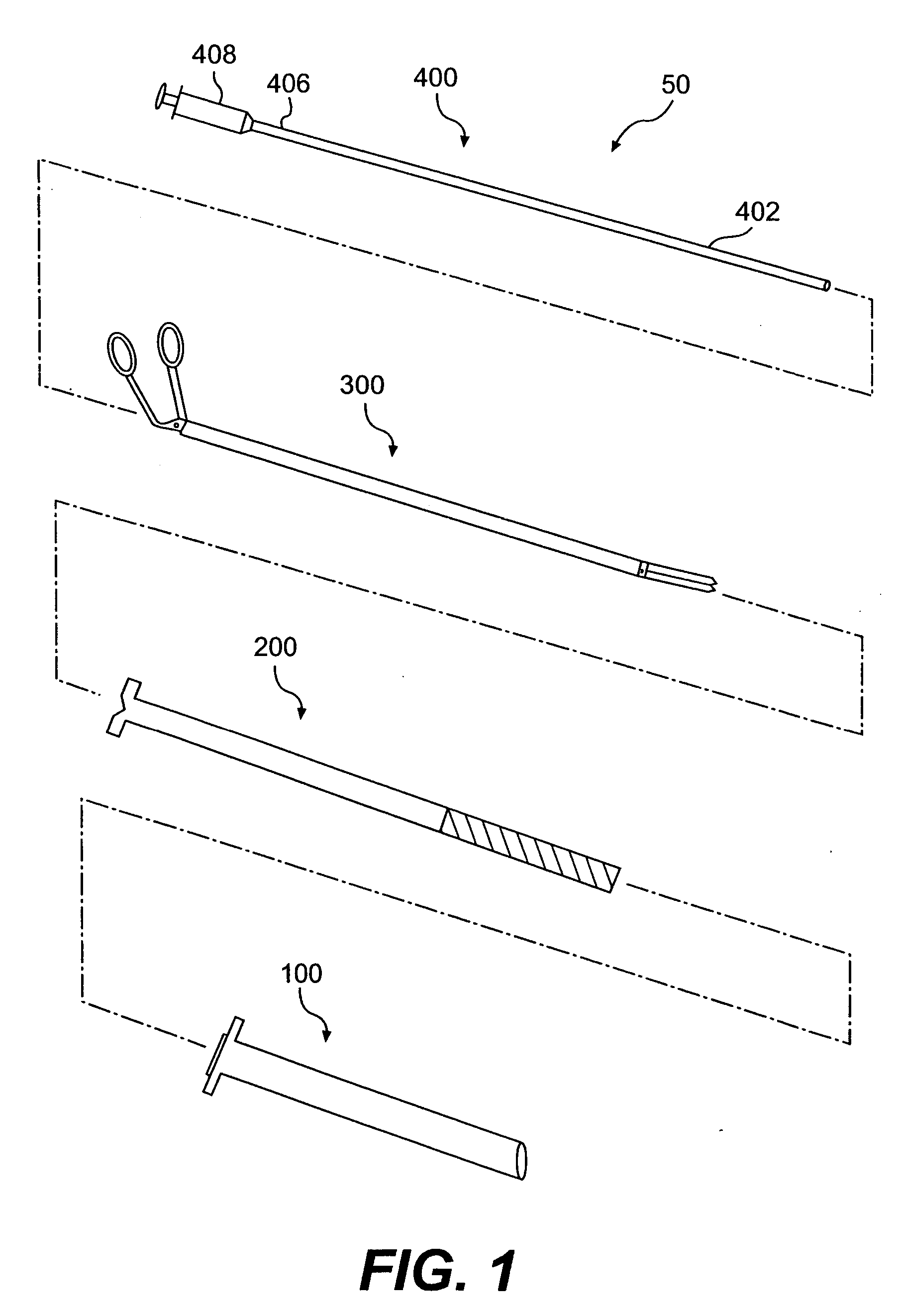
[0031]FIG. 1 shows a tool set 50 having a cannula 100, a dilator extractor 200, a grasper 300, and syringe device 400. As shown in FIGS. 1 and 9, syringe 400 is insertable in grasper 300, which is in turn insertable in dilator extractor 200, which in turn is insertable in cannula 100 to form a multi-coaxial assembly for use in laparoscopic surgery.

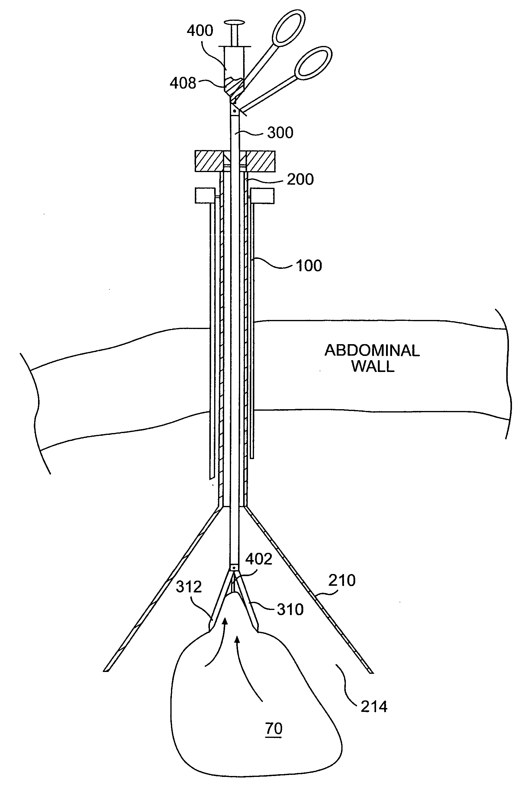
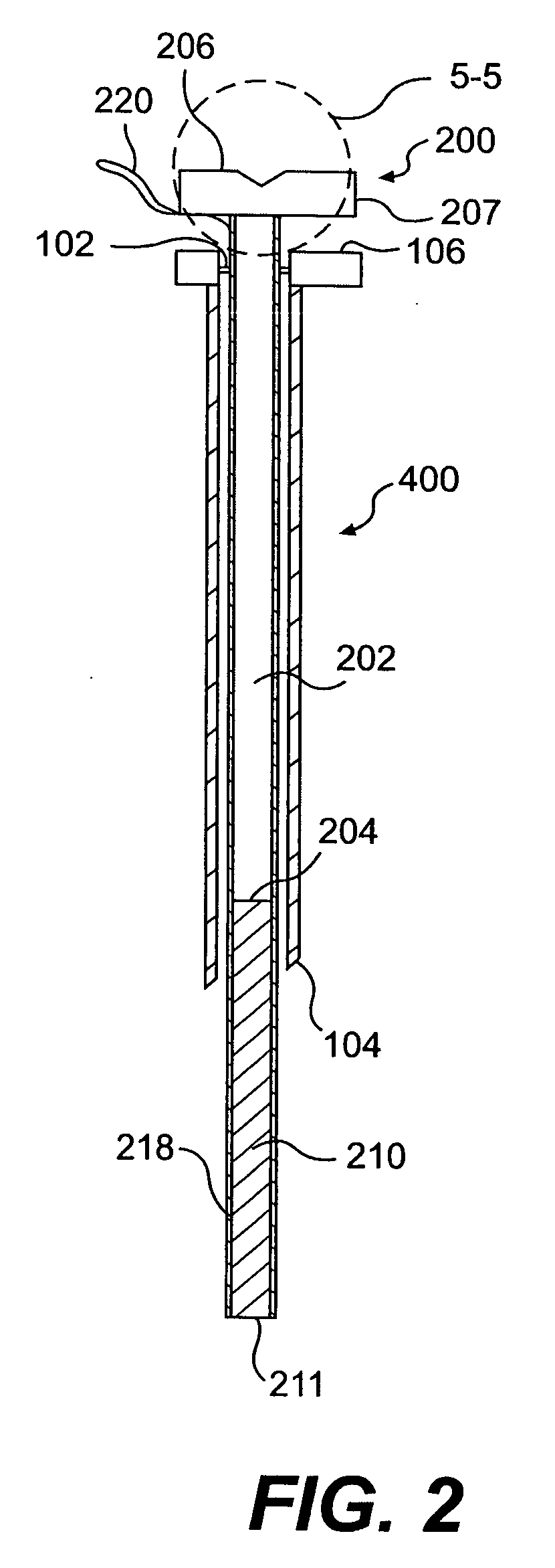
[0032] Referring to FIGS. 2-4 and 8, dilator extractor 200 is inserted into a pressurized abdominal cavity 60 through the abdominal wall of a patient. Dilator extractor 200 enters through valve 102 at trailing end 106 of cannula 100.

[0033] Dilator extractor 200 includes a body 202 having a leading end 204, a trailing end 206, a longitudi...


PUM


Abstract

A surgical dilator extractor is introduced into the abdominal cavity through a trocar cannula and expanded, forming a tissue receiving space, at the distal end. The tissue that is to be extracted is then suctioned to the dilator. The tissue is then removed from the cavity by the surgeon applying a force onto the dilator extractor that insures the elongation of the tissue and temporarily dilates the entry wound to the extent necessary for the tissue to be removed. Alternative embodiments of the surgical dilator extractor and related instrument tool sets and methods for the use thereof also are disclosed.

Description

RELATED APPLICATIONS [0001] This application is a continuation-in-part of application Ser. No. 10 / 047,122, filed Jan. 15, 2002, which claims the benefit of U.S. Provisional Application No. 60 / 261,798, filed Jan. 17, 2001; and is a continuation-in-part of application Ser. No. 10 / 680,973, filed Oct. 7, 2003, which claims the benefit of U.S. Provisional Application No. 60 / 416,665, filed Oct. 7, 2002; and U.S. Provisional Application No. 60 / 439,759, filed Jan. 13, 2003, all of which are incorporated by reference herein.BACKGROUND OF THE INVENTION [0002] The present invention relates generally to mechanical devices and methods used in laparoscopic surgical procedures to remove organs and excised tissue from internal body cavities. [0003] It will be appreciated by those skilled in the art that the use of bags or pouches to remove organs and large tissue specimen during laparoscopic surgical procedures is well known. As described, for example, in U.S. Pat. No. 5,147,371 a pouch is introduc...

Claims


Application Information

Patent Timeline
Patent Type & Authority Applications(United States)
IPC IPC(8): A61B17/26
CPCA61B17/0218A61B17/29A61B2217/005A61B2017/306A61B2017/320064A61B2017/00287
Inventor YOUNG, WAYNE P.SHIPP, JOHN I.RATCLIFF, KEITH
Owner LOGUIDICE MARK
Why Eureka
Try Eureka