
Gas laser device and gas reservoir

a laser device and gas reservoir technology, applied in the direction of laser details, gas laser construction details, active medium materials, etc., can solve the problems of waste products that are not suitable for further excitation, and achieve the effect of compact and flat design and reduced cross-section of laser devices

Inactive Publication Date: 2015-07-07
ALLTEC ANGEWANDTE LASER LICHT TECH GMBH
View PDF77 Cites 0 Cited by
  • Summary
  • Abstract
  • Description
  • Claims
  • Application Information

AI Technical Summary

Benefits of technology

This invention provides a small and efficient laser device. The gas reservoir container is connected to the tubular space with two separate connectors, allowing for a better flow of gas and a more even distribution. The angle between adjacent resonator tubes is set to improve coupling of the laser light. The resonator tubes can be arranged in various patterns, such as triangular, rectangular, square, U- or V-pattern, or even polygonal. A compact and flat design can be achieved by arranging the tubes in one plane. The gas reservoir tube extends parallel to at least one of the resonator tubes, which minimizes the cross-section of the laser device.

Problems solved by technology

During the operation of a gas laser device, waste products will be generated which are not suitable for further excitation.

Method used


Image

  • Gas laser device and gas reservoir
  • Gas laser device and gas reservoir
  • Gas laser device and gas reservoir

Examples


Embodiment Construction

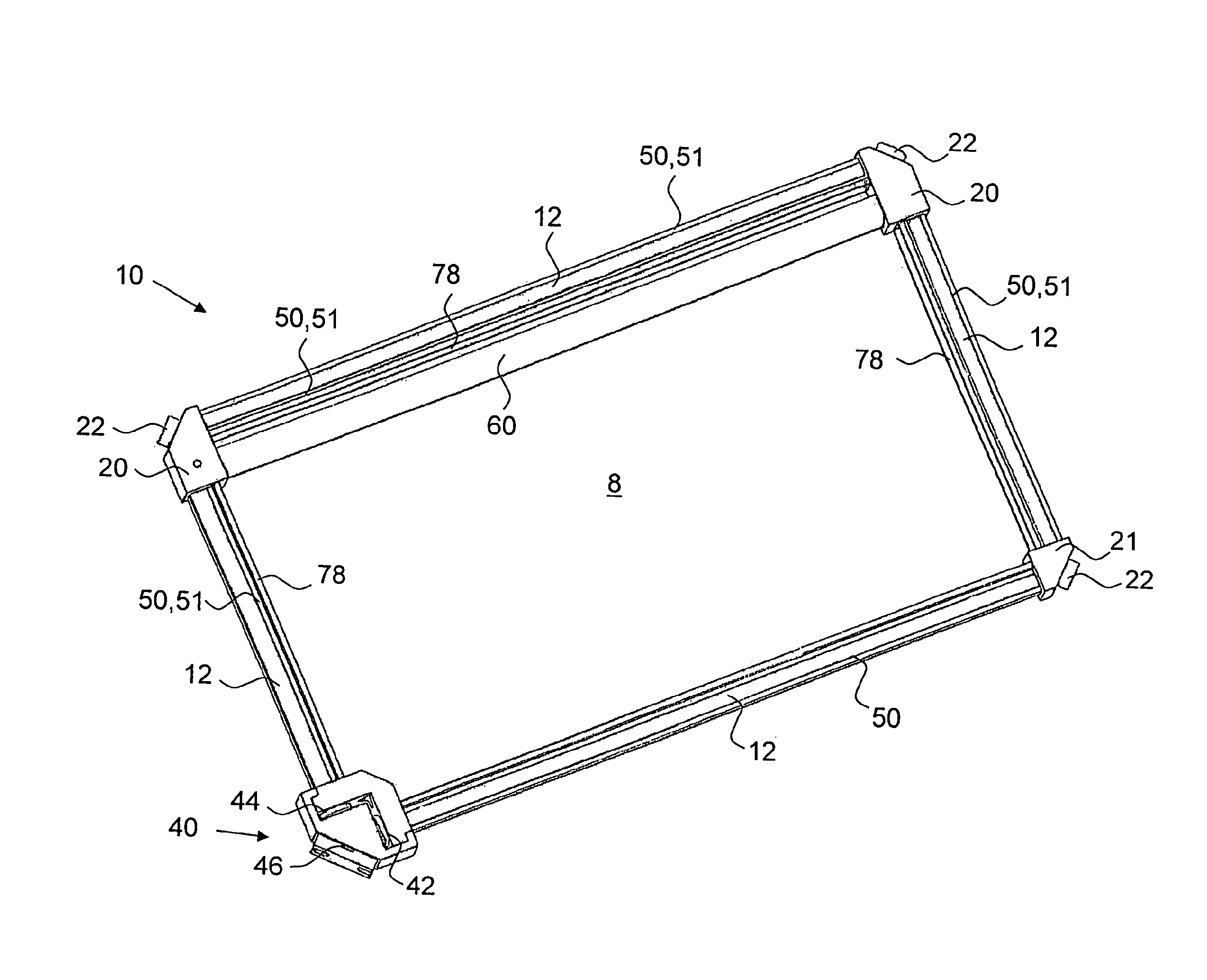
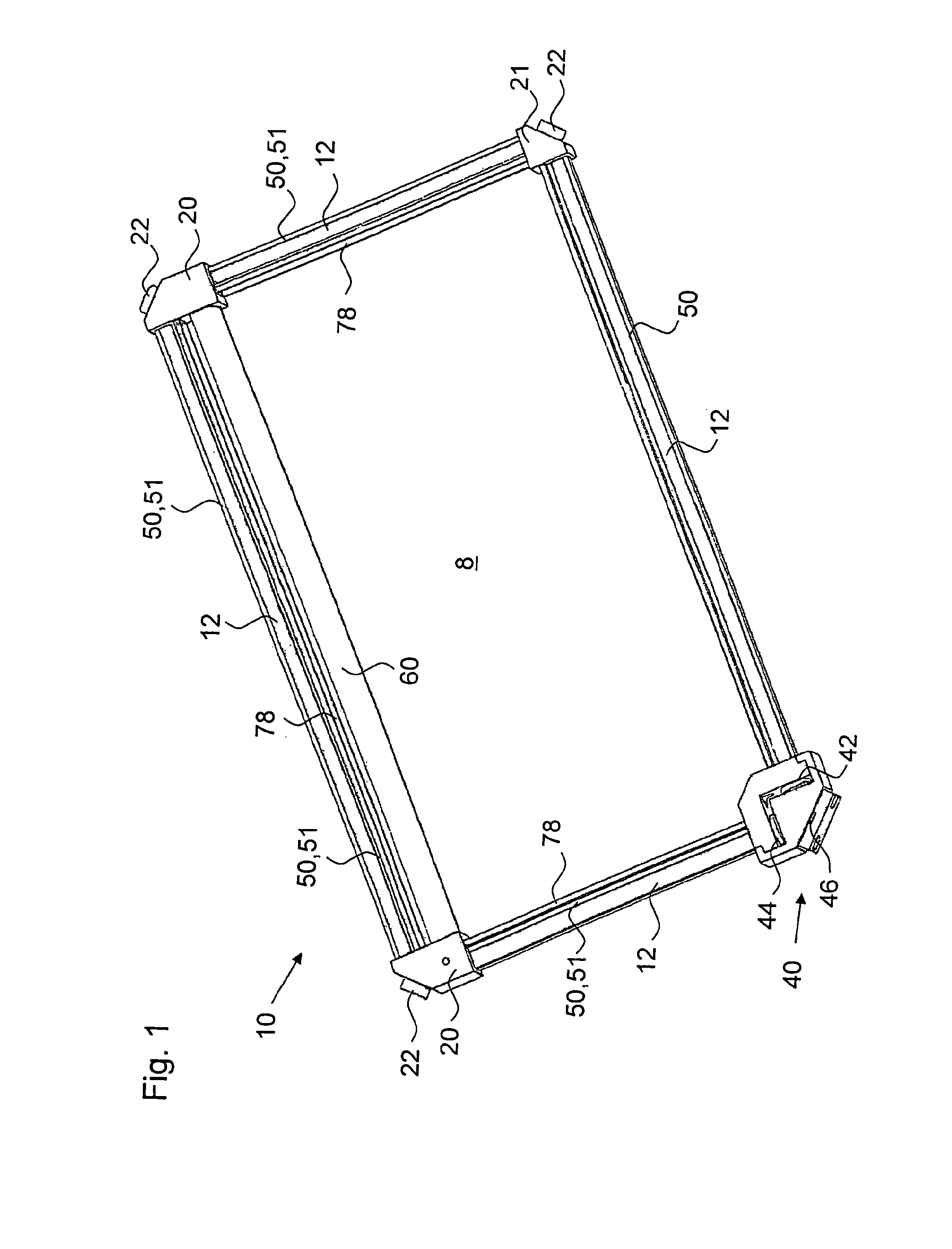
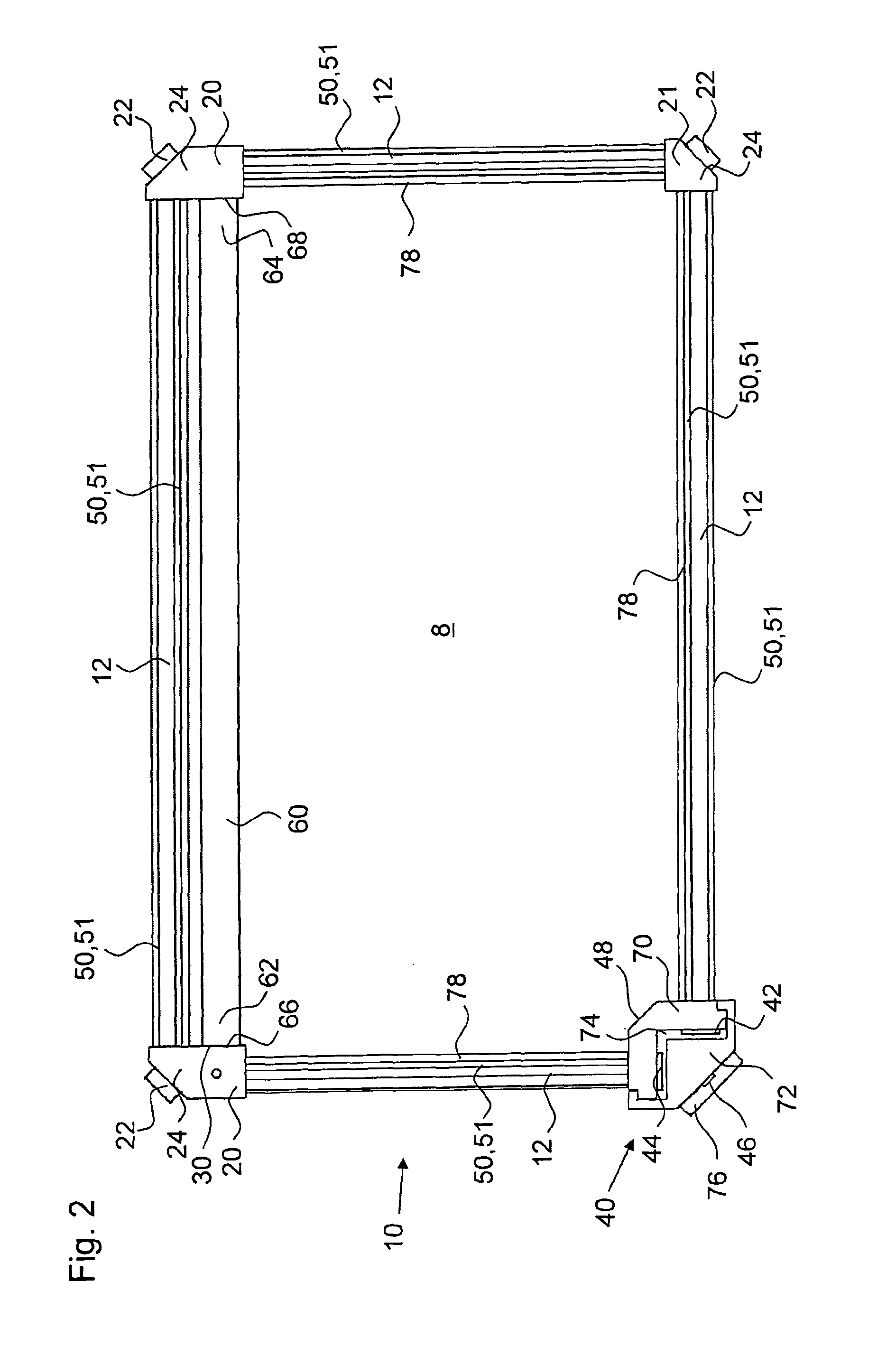
[0041]FIGS. 1 and 2 show a laser device 10, according to the invention. The laser device 10 may in particular be a laser device for marking an object by means of a laser beam. One or more of such laser devices 10 may be integrated into a marking head for marking an object.

[0042]The laser device 10 comprises a plurality of resonator tubes 12 which may in particular be alumina tubes. The resonator tubes 12 form a part of a common tubular space which may be referred to as the resonator of the laser device 10. The resonator tubes 12 are at least partially enclosed by excitation means 50 in the form of radio frequency electrodes 51 for exciting a gas contained in the resonator tubes 12. The electrodes 51 extend substantially along the entire length of the resonator tubes 12 for exciting a gas contained therein.

[0043]In the shown embodiment the laser device 10 comprises four resonator tubes 12 arranged in a square. However, instead of a square resonator the resonator may also take the sha...


PUM


Abstract

The invention refers to a laser device comprising a tubular space formed by at least two resonator tubes (12) for a gas to be excited, excitation means (50) for each of the at least two resonator tubes for exciting the gas in the resonator tube for generating laser light, a partially reflecting output coupler (42) for coupling out a laser beam, and at least one gas reservoir container (60) which forms a gas reservoir, the gas reservoir container being free of excitation means and in fluidic communication with the tubular space, wherein the gas reservoir container is arranged between the at least two resonator tubes and connected to the tubular space at two separate connecting portions (20).

Description

FIELD OF THE INVENTION[0001]The invention refers to a gas laser device.RELATED ART[0002]During the operation of a gas laser device, waste products will be generated which are not suitable for further excitation. For example, in a CO2 laser gas components such as H2, H2O and CO are formed during the operation of the laser. Therefore, the gas in the laser device either has to be regenerated in certain intervals or a constant flow of fresh gas has to be provided.[0003]In order to enhance the time between two successive regenerations it is known to connect a gas container to the tubular space of the laser device in which gas excitation takes place. The gas container provides fresh gas to the tubular space.[0004]WO 02 / 43197 discloses a gas laser comprising a discharge tube in which laser discharge occurs. A gas reservoir is in fluid communication with the interior of the discharge tube through two different passages.[0005]U.S. Pat. No. 4,189,687 describes a gas laser having a laser tube ...

Claims


Application Information

Patent Timeline
Patent Type & Authority Patents(United States)
IPC IPC(8): H01S3/22H01S3/0975H01S3/03H01S3/07
CPCH01S3/03H01S3/076H01S3/0975
Inventor ARMBRUSTER, KEVIN L.GILMARTIN, BRAD D.KUECKENDAHL, PETER J.RICHARD, BERNARD J.RYAN, DANIEL J.
Owner ALLTEC ANGEWANDTE LASER LICHT TECH GMBH
Learn More