
Thermoelectric device

a technology of thermoelectric cooler and thermoelectric device, which is applied in the manufacture/treatment of thermoelectric devices, thermoelectric device details, and thermoelectric devices with peltier/seeback effect, etc., can solve the problems of reducing the overall performance, reducing the cooling efficiency of state of the art thermoelectric coolers, and a lot of heat, so as to reduce any detrimental effect, facilitate the manufacturing process, and enhance the effect of effectiveness

Active Publication Date: 2020-09-01
IEE INT ELECTRONICS & ENG SA
View PDF11 Cites 0 Cited by
  • Summary
  • Abstract
  • Description
  • Claims
  • Application Information

AI Technical Summary

Benefits of technology

The device achieves improved thermoelectric performance by increasing electrical conductivity while decreasing thermal conductivity, resulting in more efficient heat transfer and reduced energy consumption, enabling effective cooling across a wide range of applications from sub-micrometer to mm-scale.

Problems solved by technology

One major drawback, however, is that the cooling efficiency of state of the art thermoelectric coolers is rather low and that they dissipate a lot of heat which reduces the overall performance considerably.
Hence, improving the figure of merit zT in thermoelectric materials is still a big challenge in material science, hampering the development of novel, more efficient thermoelectric cooling devices.
Beside the low figure of merit, the heat transfer in state of the art thermoelectric materials is also rather inefficient due to heat dissipation at elevated operation current I, such that the thermoelectric cooler consumes more power than it effectively transports.
The former causes internal heating through I2R losses.
This is a very critical issue because it imposes a lot more heat on the heat sink to cool.
This illustrates that prior art thermoelectric cooling devices add a lot of excess heat to the system, which considerably reduces the performance of the overall cooling process.
Based on the Peltier effect, the thermoelectric device may create a temperature difference, when a voltage is applied to it.
However, this is still not verified experimentally.
Therefore, any detrimental effect on the total conductivity can be limited or even negligible.
Thus, the minimal size of the grooves is mostly limited by the manufacturing process.
Due to its insulating property, it does not allow for any (or at least any substantial) current between the opposite side surfaces.

Method used


Image

  • Thermoelectric device
  • Thermoelectric device
  • Thermoelectric device

Examples


first embodiment

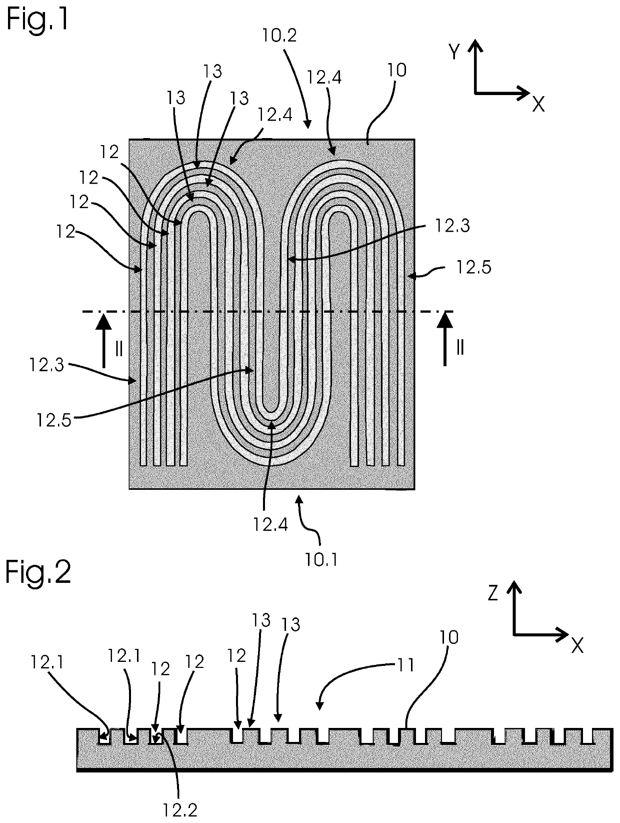
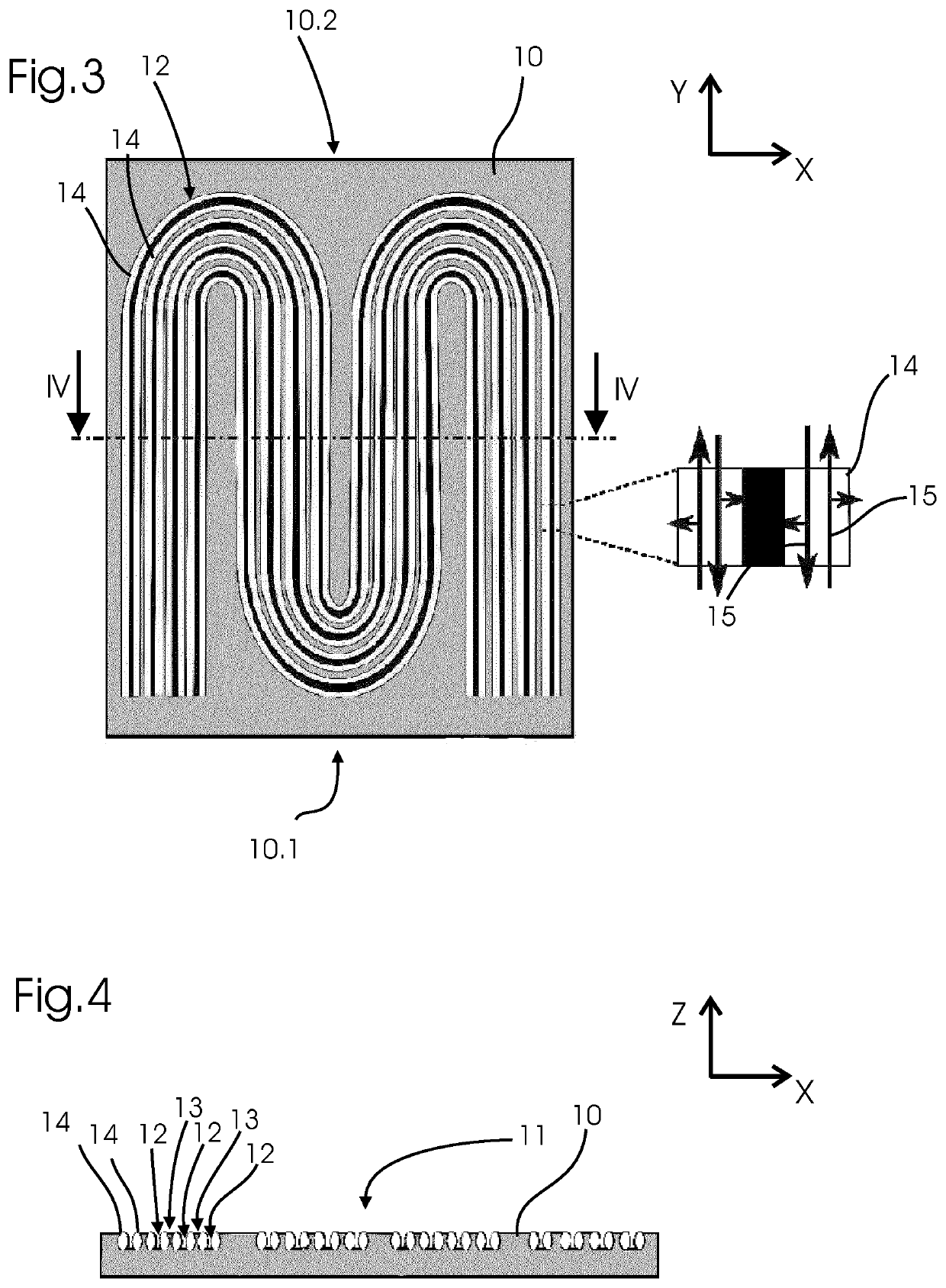
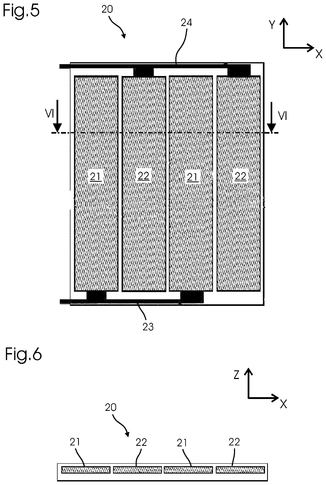
[0062]FIGS. 10 and 11 show a thermoelectric device 1 according to the present invention. It comprises a channel portion 50 that is similar to the one shown in FIG. 9. However, on each channel layer 10, three first electrodes 16, 17, 18 are disposed at the first end 10.1, while two second electrodes 19 are disposed at the second end 10.2. The central first electrode 17 and the second electrodes 19 are each disposed on a turning groove 12.4 and extend from an n-region 10.3 to a p-region 10.4. The first electrodes 16-18 comprise a first terminal electrode 16 and a second terminal electrode 18, which are connected to a voltage supply 100. Although not shown explicitly, the first terminal electrodes 16 of all channel layers 10 are connected with each other (and with the voltage supply 100) and the second terminal electrodes 18 of all channel portions 10 are connected with each other as well. The same metals that are used for the positive and negative electrodes 21, 22 may be used for the...

second embodiment

[0065]FIG. 12 is a top view of a thermal electric element 1 according to the invention. The general design is similar to the thermoelectric element 1 shown in FIGS. 10 and 11. However, in this case, there is only one meandering groove 12 having a total of five n-grooves 12.3 and five p-grooves 12.5. Accordingly, there are six first electrodes 16, 17, 18 and five second electrodes 19. It is understood that the total number of n-grooves 12.3 and p-grooves 12.5, respectively, can be greater or smaller than five. Also, although FIG. 12 shows only a single meandering groove 12, this embodiment could be modified to include a plurality of meandering grooves 12.

[0066]FIGS. 13 and 14 show a third embodiment of a thermoelectric element 1 according to the invention. In contrast to the first and second embodiment, it comprises a plurality of consecutive channel portions 50. The channel portions 50 are identical and similar to the design shown in FIG. 10, although they only comprise one meanderi...


PUM

PropertyMeasurementUnit
relative permittivityaaaaaaaaaa
thicknessaaaaaaaaaa

Abstract

A thermoelectric device having a channel portion which includes at least one channel layer made of a topological insulator material and having a top surface with at least one groove, wherein each side surface of each groove includes a conducting zone with a pair of topologically protected one-dimensional electron channels. Each channel layer includes at least one n-region and at least one p-region which are alternatingly disposed and extend from a first end to a second end of the channel layer, each n-region comprising at least one n-groove running from a first electrode at the first end to a second electrode at the second end and each p-region includes at least one p-groove running from a second electrode to a first electrode, wherein the first and second electrodes are alternatingly disposed to connect the p-grooves and n-grooves of neighboring regions, whereby all p-grooves and n-grooves are connected in series.

Description

TECHNICAL FIELD[0001]The invention relates to a thermoelectric device and to an integrated circuit comprising such a thermoelectric device.BACKGROUND OF THE INVENTION[0002]Thermoelectric cooling devices which are based on the Peltier effect allow cooling below ambient temperature and are more compact and less expensive than comparable cooling systems. Moreover, they have no moving parts and do not require any maintenance. One major drawback, however, is that the cooling efficiency of state of the art thermoelectric coolers is rather low and that they dissipate a lot of heat which reduces the overall performance considerably.[0003]The performance and efficiency of a thermoelectric module can directly be related to its thermoelectric figure of merit zT as well as to its temperature gradient ΔT which is defined by the two temperatures Th and Tc at the hot and the cold side of the module, respectively. The thermoelectric figure of merit, which describes the ability of a material to conv...

Claims


Application Information

Patent Timeline
Patent Type & Authority Patents(United States)
IPC IPC(8): H01L35/04H01L35/32H01L35/34H10N10/17H10N10/01H10N10/81
CPCH01L35/04H01L35/32H01L35/34H10N10/17H10N10/81H10N10/01
Inventor PAULY, CHRISTIAN
Owner IEE INT ELECTRONICS & ENG SA
Learn More