
Minimized cross-section sensor package

a sensor package and cross-section technology, applied in the field of magnetic sensors, can solve the problems of reducing the overall size and cost of the sensor package, reducing the cost of handling the bare die, and increasing the complexity of the mechanical system

Inactive Publication Date: 2005-06-02
WOLFF CONTROLS
View PDF27 Cites 0 Cited by
  • Summary
  • Abstract
  • Description
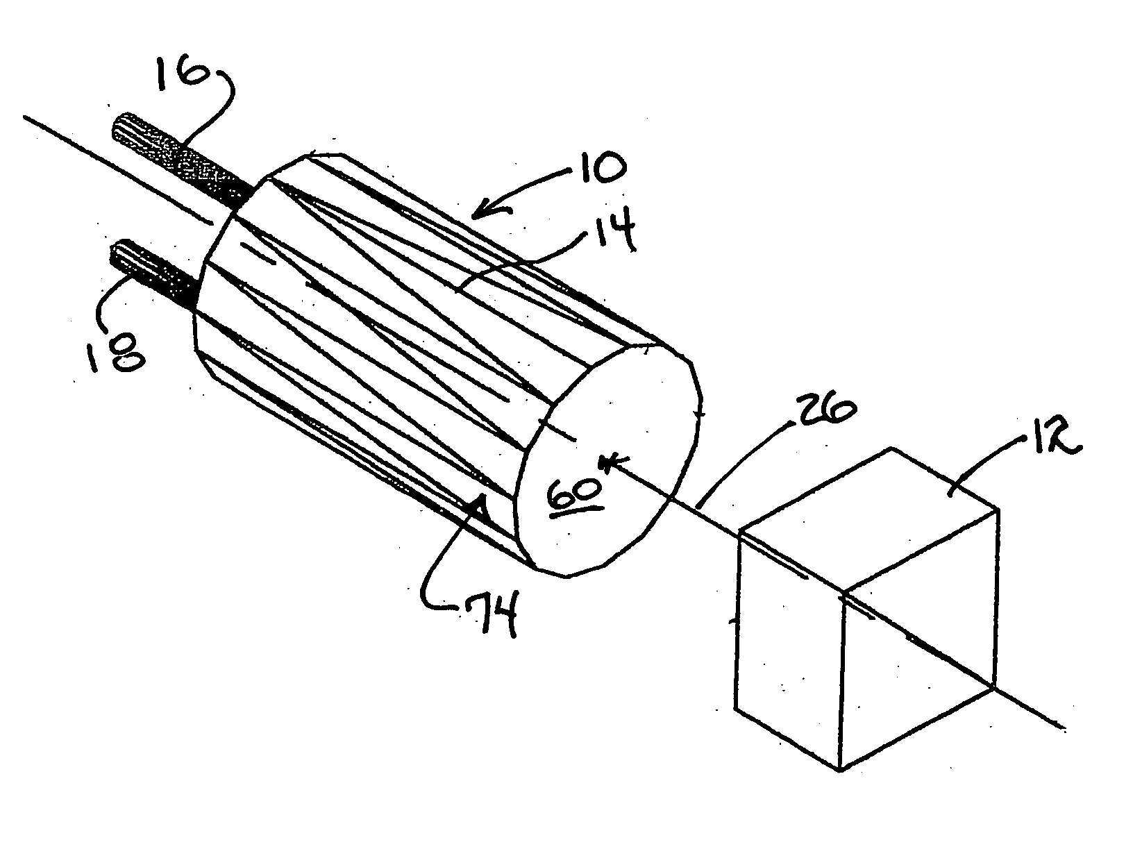
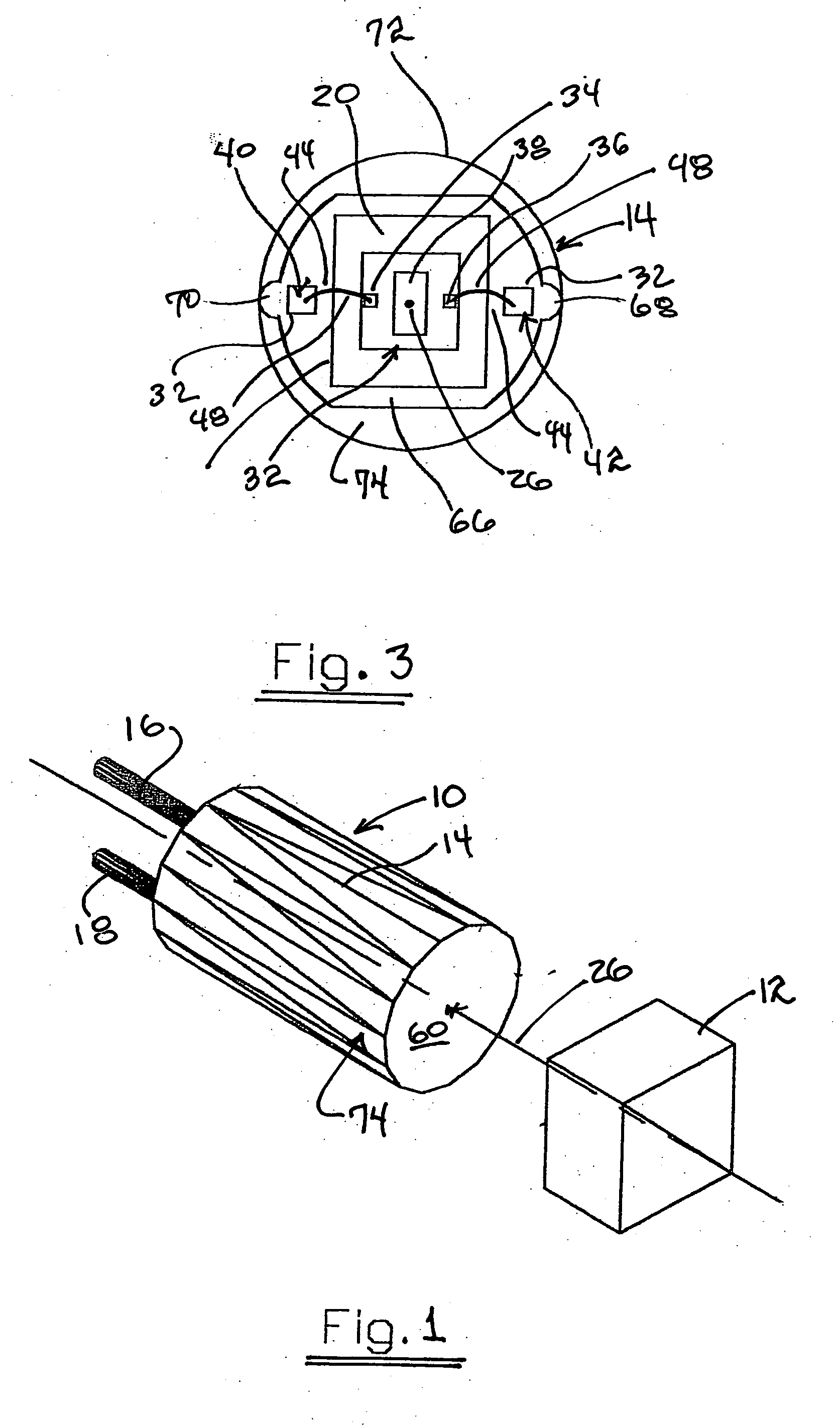
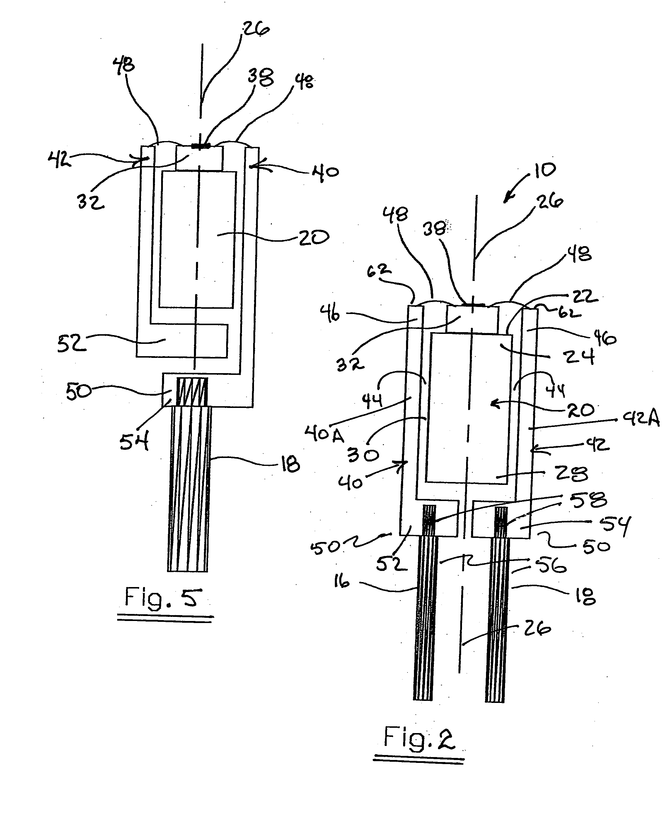
  • Claims
  • Application Information

AI Technical Summary

Benefits of technology

[0008] Each of the surfaces of the proximal ends of the at least two elongate pins and each of the at least two bond pads may have the wire connection therebetween lying within a common flat plane extending perpendicular to the central axis. A girth dimension for each offset may be greater than a girth dimension for each elongate pin, thus allowing a smaller gauge connection for each insulated wire to be connected thereto. In one embodiment, a first encapsulation secures the at least two electrically conductive elongate pins in a fixed position relative to the magnet and an enclosing thereof. Alternatively, a second encapsulation may enclose the proximity sensing circuitry and the first encapsulation therein while having only the insulated wires extending therefrom.
[0009] One embodiment of the invention may include a cylindrical sensor package that has its internal components and materials optimally configured and orientated as to maximize circuit sensitivity, and providing a minimized cross section for use in a mechanical systems which has limited space. The sensor package may contain an sensing element that is mounted directly to the center of a magnet then both are aligned so they are optimally placed in the center of the radial axis of the cylindrical sensor package to allow for the maximum sensor signal output with no change due to the relative rotation angle between the sensor and the target being sensed.
[0011] A molding process may be used to encapsulate the assembly providing the final cylindrical shape and giving the assembly a hermetic seal and protection from a harsh environment.

Problems solved by technology

As mechanical systems become more complex and costly there has developed a need to reduce the overall sensor package size and cost.
For applications where size is not a consideration a prepackaged device is appropriate as handling the bare die can be costly.
Complexity, size, durability, and cost are all issues for these types of sensors.
There have been attempts to simplify the packaging using unpackaged sensing elements but they fall short of addressing all the aforementioned criteria.

Method used


Image

  • Minimized cross-section sensor package
  • Minimized cross-section sensor package
  • Minimized cross-section sensor package

Examples


Embodiment Construction

[0020] The present invention will now be described more fully hereinafter with reference to the accompanying drawings, in which preferred embodiments of the invention are shown. This invention may, however, be embodied in many different forms and should not be construed as limited to the embodiments set forth herein. Rather, these embodiments are provided so that this disclosure will be thorough and complete, and will fully convey the scope of the invention to those skilled in the art. Like numbers refer to like elements throughout, and prime notation is used to indicate similar elements in alternate embodiments.

[0021] By way of example, mechanical systems such as internal combustion engines usually contain a significant number of moving objects. For instance, there are usually multiple cylinders in diesel engines utilizing fuel injectors each containing a moving valve or other object that must be monitored for efficient or safe operation. Each injector requires a separate sensor t...


PUM


Abstract

A proximity sensor is carried within a small diameter package and includes a magnet for providing a desirable magnetic field for operation of proximity sensing circuitry carried along a central axis to allow for a maximum sensor signal output with no change due to a relative rotation angle between the sensor and a target being monitored. Electrical contact pins include an offset positioned near the central axis for permitting a desirable small gauge insulated wire to be connected the sensor.

Description

CROSS-REFERENCE TO RELATED APPLICATIONS [0001] This application claims the benefit of U.S. Provisional Application having Ser. No. 60 / 524,799 for Offset Compensated Position Sensor, and U.S. Provisional Application having Ser. No. 60 / 524,919 for Minimized Cross-Section Sensor Package, both having filing date Nov. 25, 2003, the disclosures of which are herein incorporated by reference in their entirety, both commonly owned with the instant application.FIELD OF THE INVENTION [0002] The present invention relates to magnetic sensors and more particularly the packaging of said sensor to reduce package size and cost while providing optimum circuit sensitivity and improving durability. BACKGROUND OF THE INVENTION [0003] Sensing devices which are used to measure proximity or displacement of an object in a mechanical system are common in industry. As mechanical systems become more complex and costly there has developed a need to reduce the overall sensor package size and cost. Many mechanica...

Claims


Application Information

Patent Timeline
Patent Type & Authority Applications(United States)
IPC IPC(8): G01B7/00G01B7/14G01B7/30G01D11/24
CPCG01D11/245G01B7/003
Inventor STETTLER, RICHARD W.SMITH, MARSHALL E. JR.
Owner WOLFF CONTROLS
Learn More