
Method of anchoring a first object in a second object

a technology of second objects and anchoring methods, applied in the direction of key type connection, fastening means, mechanical equipment, etc., can solve the problems of causing cracks or other damage, a large mechanical load on the second object, and a high risk of such damage,

Active Publication Date: 2020-09-22
WOODWELDING +1
View PDF17 Cites 0 Cited by
  • Summary
  • Abstract
  • Description
  • Claims
  • Application Information

AI Technical Summary

Benefits of technology

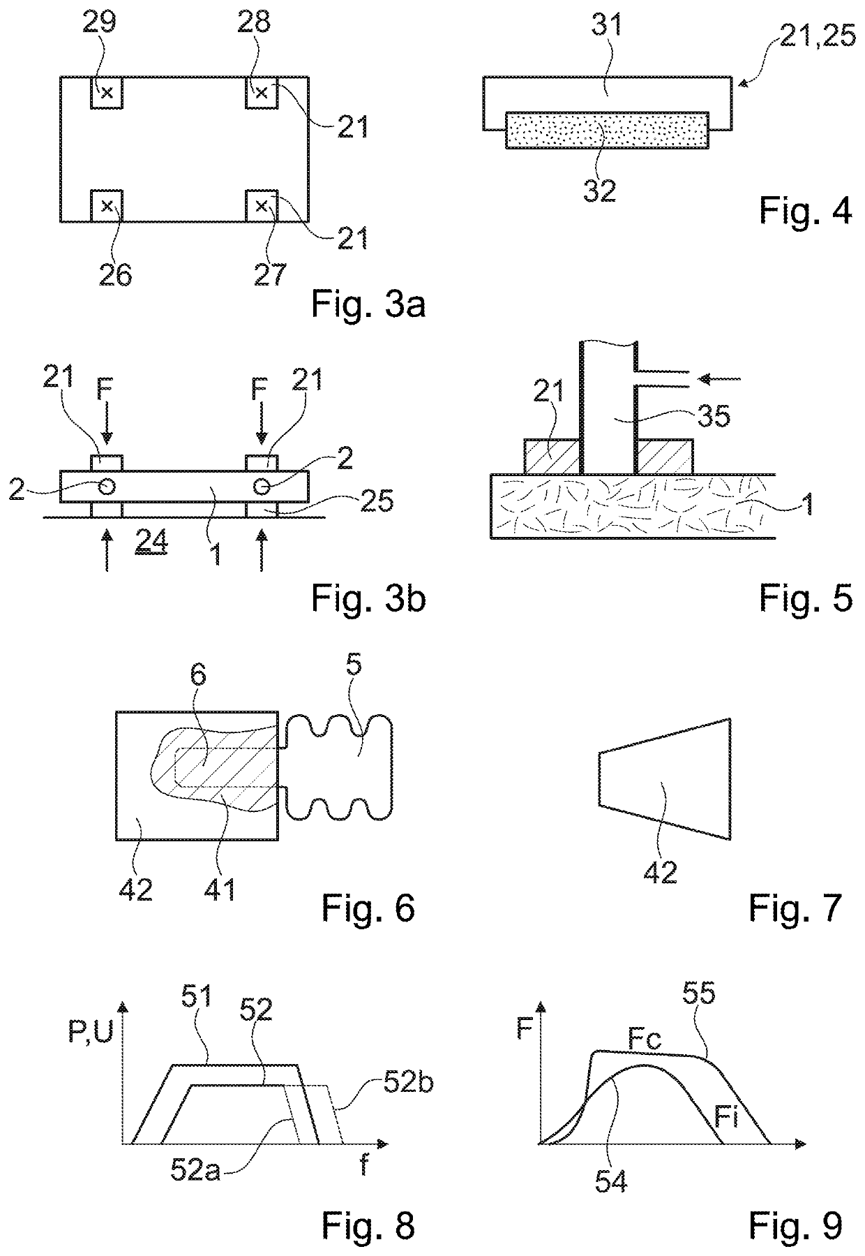
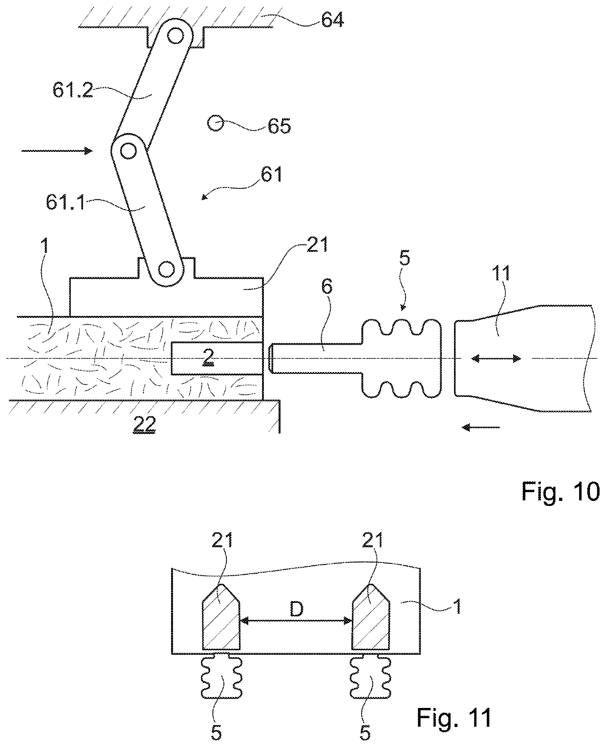
The present invention provides a method for joining two objects using a clamping force to reduce the risk of damage to the second object caused by inserting the insert portion in the opening. The clamping force also reduces the risk of cracks and visible bulges in the second object and can counteract adverse effects of hydrostatic pressure on the first object. The clamping force can be controlled and adapted to changing requirements. The method is simple to set up, requires no additional energy input, and automatically adapts to the circumstances. The small clamping surface areas make possible that the movable mass of clamping elements is small, which may be a further advantage in a high speed process. The handling may be accelerated while the board remains protected from overly high impact due to too high clamping element moments.

Problems solved by technology

Especially if the second, alternative approach (with establishing an interference fit prior to the anchoring step) but also on certain embodiments of the first approach in which during the step of applying vibration and force, for example described in WO 2008 / 080239, a slightly oversized portion of the insert is pressed into the opening, the second object may be subject to a considerable mechanical load due to the interference force.
Depending to the composition of the penetrable material or possibly other materials of the anvil object, there may be a risk of cracks or other damages (such as portions flaking off) being caused by the introduction of the insert portion into the opening prior to the step of anchoring.
This risk of such damages is particularly high if the second object is board shaped at least in sections and if the opening is an opening in the narrow side face of the board, in particular if the dimensions of the opening are of a same order of magnitude as the thickness of the board (board section) so that there is not too much of the penetrable material between the opening and the broad surfaces.

Method used


Image

  • Method of anchoring a first object in a second object
  • Method of anchoring a first object in a second object
  • Method of anchoring a first object in a second object

Examples


Embodiment Construction

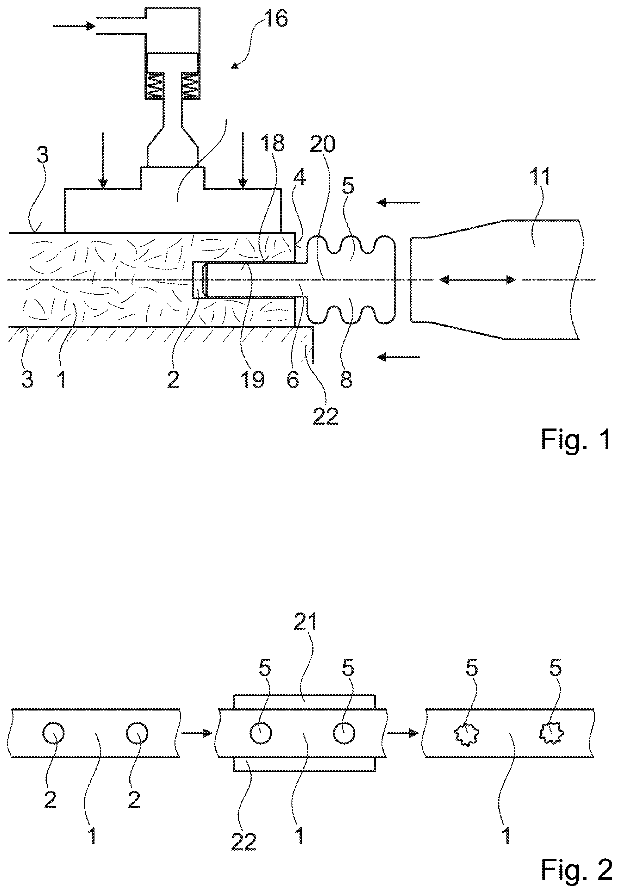
[0074]FIG. 1 depicts a board 1 of for example chipboard being the second object in a method according to the invention. The board has two opposed broad surfaces 3 and a narrow side face 4 with a blind opening 2. A fitting element 5 having a head portion 8 and an insert portion 6 serves as the first object in the method. The fitting element 5 in the depicted embodiment includes a thermoplastic material, for example a polyamide and is, according to an embodiment, made entirely or almost entirely from this thermoplastic material, whereas in alternative embodiments it may include a core of a not thermoplastic material with a coating of a thermoplastic material.

[0075]The insert portion 6 has a slightly oversized cross section compared to the opening 2 so that the insert portion is held in an interference fit in the opening 2 after the insert portion 6 has been introduced, for example by a pressing force acting in a direction of an axis 20 of the opening. Due to the interference fit, oppo...


PUM

PropertyMeasurementUnit
clamping pressureaaaaaaaaaa
pressureaaaaaaaaaa
pressureaaaaaaaaaa

Abstract

A method for joining two objects by anchoring an insert portion provided on a first object in an opening provided on a second object. The anchorage is achieved by liquefaction of a thermoplastic material and interpenetration of the liquefied material and a penetrable material, the two materials being arranged on opposite surfaces of the insert portion and the wall of the opening. During the step of inserting the insert portion in the opening and / or during anchorage a clamping force is applied to opposing surfaces of the second object to prevent the second object from cracking or bulging.

Description

BACKGROUND OF THE INVENTION[0001]Field of the Invention[0002]The invention is in the field of mechanical engineering and construction and concerns a method for joining two objects. A first one of the object includes an insert portion and the other object includes an opening, and, for the two objects to be joined, the insert portion is anchored in the opening, wherein, in the anchoring area, one of the objects includes a solid material having thermoplastic properties, and the other object includes a solid material that is penetrable by the material having thermoplastic properties when liquefied. The penetrable material of the second object is, e.g., fibrous or porous. Especially, it may be a wood-based material such as wood, chipboard, etc. The second object may be a board, and the opening may be an opening in the narrow side face of the board.[0003]Description of the Related Art[0004]From e.g. the publications WO 96 / 01377 (Createc), WO 98 / 042988 (Woodwelding) and WO 2006 / 002569 (Woo...

Claims


Application Information

Patent Timeline
Patent Type & Authority Patents(United States)
IPC IPC(8): B29C65/08B29C65/00B29C65/64B29C65/60B29C65/56F16B3/00B29C65/78B29C65/48B29C65/50B29C65/06B29K309/08B29K677/00
CPCB29C66/474B29C66/7486B29C66/7212B29C66/1122B29C65/5057B29C66/727B29C65/564B29C66/41B29C65/08B29C66/006B29C66/729B29C66/02242B29C65/7841B29C66/30223B29C66/7392B29C66/8322B29C66/30326B29C66/43B29C66/30221B29C65/608B29C65/604F16B3/005B29C65/4815B29C65/565B29C66/81417B29C66/7487B29C66/9592B29C66/30321B29C65/645B29C66/81429B29C66/1142B29C66/126B29C65/48B29C65/0618B29K2677/00B29K2995/0046B29K2309/08B29C66/71B29K2023/06B29K2023/12B29K2025/06B29K2025/08B29K2027/06B29K2055/02B29K2059/00B29K2067/00B29K2069/00B29K2071/00B29K2077/00B29K2079/085B29K2081/04B29K2081/06B29C65/72F16B5/00
Inventor MAYER, JÖRGLEHMANN, MARIOKÄLL, HÅKANSANKARAN, MUTHUMARIAPPAN
Owner WOODWELDING
Learn More