Robot for transporting storage bins

a robot and storage bin technology, applied in the direction of load-engaging elements, program-controlled manipulators, trolleys, etc., can solve the problem of limiting the maximum number of simultaneously operating vehicles, and achieve the effect of stable pressure and better conta

Active Publication Date: 2017-05-11
AUTOSTORE TECH AS
View PDF3 Cites 22 Cited by
  • Summary
  • Abstract
  • Description
  • Claims
  • Application Information

AI Technical Summary

Benefits of technology

[0018]In an alternative embodiment the interconnecting cord is encircling the upper rotating unit but arranged outside the lower rotation unit. The latter configuration may be achieved by means of additional wheels around which the cord is encircling. The assembly of the cord and the additional wheels should then be configured to create a stable pressure onto th

Problems solved by technology

However, with this known system each vehicle assembly is covering a cross section of the underlying storage system

Method used


Image

  • Robot for transporting storage bins
  • Robot for transporting storage bins
  • Robot for transporting storage bins

Examples


first embodiment

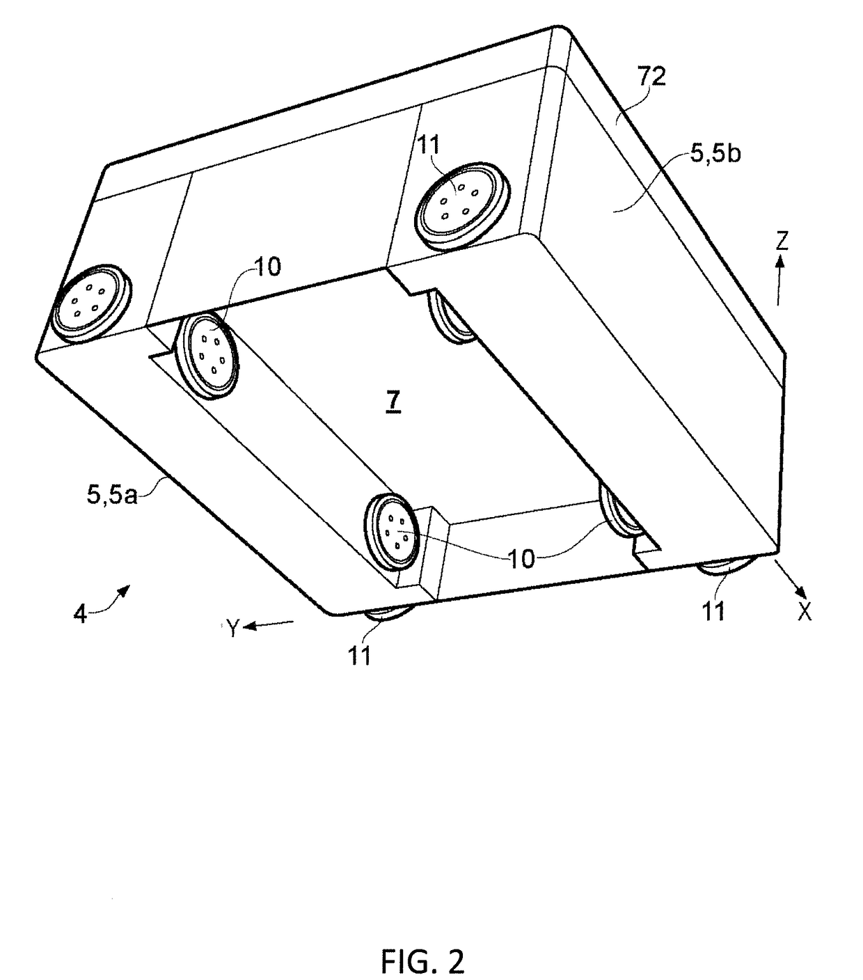
[0047]FIGS. 2 and 3 give perspective views in two different angles of a robot 1 in accordance with the invention comprising a rectangular vehicle body or framework 4 displaying a cavity 7 centrally arranged there within, a top cover 72 covering the top part of the body 4, a first set of four wheels 10 mounted inside the cavity 7 and a second set of four wheels 11 mounted at the exterior walls of the body 4. The first and second set of wheels 10,11 are oriented perpendicular to each other. For the sake of clarity a Cartesian coordinate system is shown with its X, Y and Z axes aligned along the principal directions of the rectangular vehicle body 4. The size of the cavity 7 is adapted to at least contain the largest storage bin 2 intended to be picked up by the robot 1, and preferably also a vehicle lifting device 9 (FIG. 4). The lateral area, i.e. along the X and Y directions, may be of any size relative to the prior art storage system, for example less than the lateral area of an un...

second embodiment

[0058]FIGS. 10-11 show other illustrations of the vehicle in accordance with the

[0059]A vehicle with a top cover 72 (non-removable or removable) and a vehicle body 4 covering all sides in the X,Y directions is shown in FIGS. 10 (a) and (b) observed along x direction and y direction respectively.

[0060]In the partly transparent illustration in FIG. 10 (c) a storage bin 2 may be seen arranged fully within the cavity 7. FIGS. 10 (b) and (d) show a cross sectional views along section A-A of FIG. 10 (a) and section B-B of FIG. 10 (c), revealing internal components of the vehicle 1. With reference to FIG. 10 (b), the second displacement plate 34b is shown extending from the upper part 4u of the vehicle body / framework 4, including the master wheel 30, and to the lower edge of the vehicle 1, including the slave wheels 31,31a,31b (FIG. 11).

[0061]The vehicle lifting device 9 includes the vehicle lifting device motor 9a, the lifting grips 9b situated below the lifting device plate for grabbing ...

third embodiment

[0065]A third embodiment according to the invention is shown in FIGS. 13-16, where FIGS. 13 (a) and (b) show the inventive vehicle 1 comprising a top cover 72 (non-removable or removable), a vehicle body / framework 4 covering all sides in the X,Y directions, a first set of vehicle rolling means 10,10a,31a,31b and a second set of vehicle rolling means 11. FIG. 13 (b) also shows part of the cavity 7 and part of the lifting device 9 with its lifting grips 9b and guiding pins 9c.

[0066]FIGS. 14 (a) and (c) show side views observed along x direction and y direction, respectively, of the third embodiment vehicle shown in FIG. 13. Cross sectional views along section A-A of FIG. 14 (a) and section B-B of FIG. 14 (c) are shown in FIGS. 14 (b) and (d), respectively, revealing internal components of the vehicle 1. As for the second embodiment shown in FIG. 10 (b) the second displacement plate 34b extends from the upper part 4u of the vehicle body 4 to the lower edge of the vehicle 1, including ...


PUM


Abstract

A remotely-operated vehicle assembly for picking up storage bins from a storage system and a method for changing vehicle direction includes a body displaying a cavity, a lifting device connected to the body for lifting the bin into the cavity, a displacement arrangement including a displacement motor which provides power to displace one or both of first and second sets of vehicle rolling means between a displaced state where the relevant rolling means is displaced away from the underlying system during use, and a non-displaced state where the relevant rolling means is in contact with the underlying system during use, and driving means coupled to the displacement arrangement. The driving means further includes first and second sets of rolling means connected to the body allowing movement of the vehicle along first and second directions, respectively, within the system. The first and second directions are perpendicular.

Description

TECHNICAL FIELD[0001]The present invention relates to a remotely operated vehicle assembly for picking up storage bins from a storage system as defined in the preamble of claim 1, a storage system for storage of bins and a method for changing direction of the vehicle.BACKGROUND AND PRIOR ART[0002]A remotely operated vehicle for picking up storage bins from a storage system is known. A detailed description of a relevant prior art storage system is presented in WO 98 / 49075, and details of a prior art vehicle being suitable for such a storage system is disclosed in Norwegian patent NO317366. Such a prior art storage system comprises a three dimensional storage grid containing storage bins that are stacked on top of each other up to a certain height. The storage grid is normally constructed as aluminium columns interconnected by top rails, and a number of remotely operated vehicles, or robots, are arranged to move laterally on these rails. Each robot is equipped with a lift for picking ...

Claims


Application Information

Patent Timeline
IPC IPC(8): B65G1/04
CPCB65G1/0464B25J5/02B25J9/1689B25J11/008B25J13/006B66C11/12B65G1/0478
Inventor HOGNALAND, INGVAR
Owner AUTOSTORE TECH AS
Why Eureka
Try Eureka