Supercharge Your Innovation With Domain-Expert AI Agents!

Blind rivet arrangement

a blind rivet and arrangement technology, applied in the direction of sheet joining, fastening means, screws, etc., can solve the problems of high hole face bearing pressure, deformation of the head forming portion on the blind side, and formation of a blind head, so as to increase the rigid portion. the effect of strength

Active Publication Date: 2017-05-11
NEWFREY
View PDF11 Cites 1 Cited by
  • Summary
  • Abstract
  • Description
  • Claims
  • Application Information

AI Technical Summary

Benefits of technology

The patent text describes a new type of blind rivet that is useful for joining parts together. The rivet has a very high volume, which allows it to accommodate parts that need to be folded. This design reduces surface and edge loading on the parts and has a constant closing head, which helps to avoid increasing the pressure on the parts as the rivet is clamped. Overall, this new invention makes it easier to join parts together while still controlling the pressure distribution.

Problems solved by technology

This leads to a deformation of the head forming portion on the blind side and the formation of a blind head which bears against the blind-side workpiece surface after the setting.
In the case of blind rivet sleeves which have a folding portion, the sleeve fold thus formed in some clamping thicknesses can lead to high hole face bearing pressures and also to an expansion of the bore in plastic workpieces or even to the bursting of components particularly when small edge spacings are intended to be produced.

Method used


Image

  • Blind rivet arrangement
  • Blind rivet arrangement
  • Blind rivet arrangement

Examples


Embodiment Construction

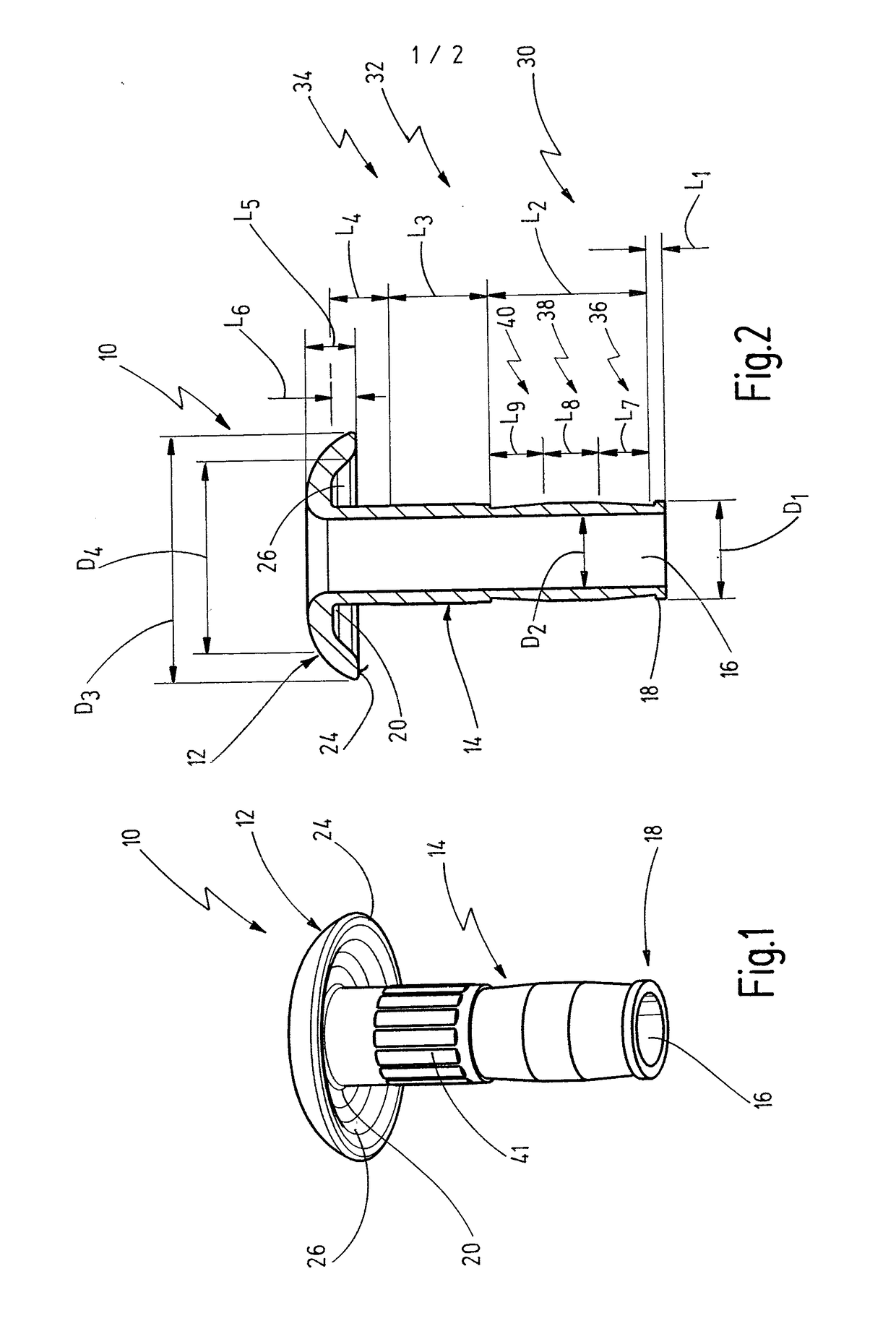
[0050]A first embodiment of a blind rivet sleeve according to the invention is shown in FIGS. 1 and 2 and designated generally by 10.

[0051]The blind rivet sleeve 10 has a sleeve head 12 and a sleeve shank 14 adjoining the sleeve head 12. The blind rivet sleeve 10 has a through-opening 16 which passes through the sleeve shank 14 and the sleeve head 12 and which is oriented axially. The sleeve shank 14 has a blind-side end 18 facing away from the sleeve head 12 and also a head-side end 20 facing the sleeve head 12.

[0052]The sleeve head 12 has a bearing face 24 pointing in the direction of the sleeve shank 14 and intended to bear against a visible workpiece. In the present case, an axial recess 26 is formed on the sleeve head 12 in the region of the bearing face 24 in such a way that the sleeve head 12 extends from the head-side end 20 of the sleeve shank 14 in the manner of a mushroom head.

[0053]The sleeve shank 14 has a head forming portion 30 adjacent to the blind-side end 18. Furth...


PUM


Abstract

Blind rivet sleeve for a blind rivet, having a sleeve head which has a bearing face for bearing against a visible workpiece surface, and having a sleeve shank, wherein the blind rivet sleeve has a through-opening through which a mandrel can be guided, wherein the sleeve shank has a head forming portion which, during the setting of the blind rivet, is designed to form a blind head, and has a folding portion which is arranged between the head forming portion and the sleeve head and which, during the setting of the blind rivet, is designed to form a sleeve fold for the purpose of achieving a clamping thickness compensation.In this arrangement, the sleeve head has in the region of the bearing face an axial recess for receiving at least part of the sleeve fold formed during the setting.

Description

FIELD OF THE INVENTION[0001]The present invention relates to a blind rivet sleeve for a blind rivet, having a sleeve head which has a bearing face for bearing against a visible workpiece surface, and having a sleeve shank, wherein the blind rivet sleeve has a through-opening through which a mandrel can be guided, wherein the sleeve shank has a head forming portion which, during the setting of the blind rivet, is designed to form a blind head, and has a folding portion which is arranged between the head forming portion and the sleeve head and which, during the setting of the blind rivet, is designed to form a sleeve fold for the purpose of achieving a clamping thickness compensation.BACKGROUND OF THE INVENTION[0002]Furthermore, the present invention relates to a blind rivet having a mandrel and a blind rivet sleeve of this type, wherein the mandrel has a blind-side mandrel head for bearing in the region of a blind-side end of the sleeve shank, and also to a blind rivet connection of ...

Claims


Application Information

Patent Timeline
Patent Type & Authority Applications(United States)
IPC IPC(8): F16B19/10F16B5/04
CPCF16B5/04F16B19/1054
Inventor SCHNEIDER, STEFANBAUMANN, HORST
Owner NEWFREY
Features
  • R&D
  • Intellectual Property
  • Life Sciences
  • Materials
  • Tech Scout
  • Unparalleled Data Quality
  • Higher Quality Content
  • 60% Fewer Hallucinations
Learn More