Final drive device

Active Publication Date: 2017-05-11
NISSAN MOTOR CO LTD
View PDF1 Cites 1 Cited by
  • Summary
  • Abstract
  • Description
  • Claims
  • Application Information

AI Technical Summary

Benefits of technology

[0009]Therefore, an object of the present invention is to provide a final d

Problems solved by technology

Consequently, space for the differential case is required between the differential gear mechanism and the housing, which in

Method used


Image

  • Final drive device
  • Final drive device
  • Final drive device

Examples


Example

[0051]FIGS. 5 to 7 illustrate the final drive device according to the second embodiment to which this invention is applied. FIG. 5 is a cross-sectional view of the principle part of the final drive device according to the present embodiment, and FIGS. 6 and 7 are a perspective view and a cross-sectional view, respectively, of the principle part of the final drive device of a modified example. In the present embodiment, a configuration is added to the first embodiment, in which the boss portion 34 of either one side gear 31B (or 31A) is extended to the proximal end portion of the pinion mate shaft 33. The same devices as the first embodiment are given the same reference symbols, and the explanations thereof are omitted or simplified.

[0052]In the final drive device illustrated in FIG. 5, the boss portion 34 of either one (the other, in the illustrated example) of the side gears 31B (31A) is extended to an area up to the proximal end portions of the pinion mate shafts 33. Along with th...


PUM


Abstract

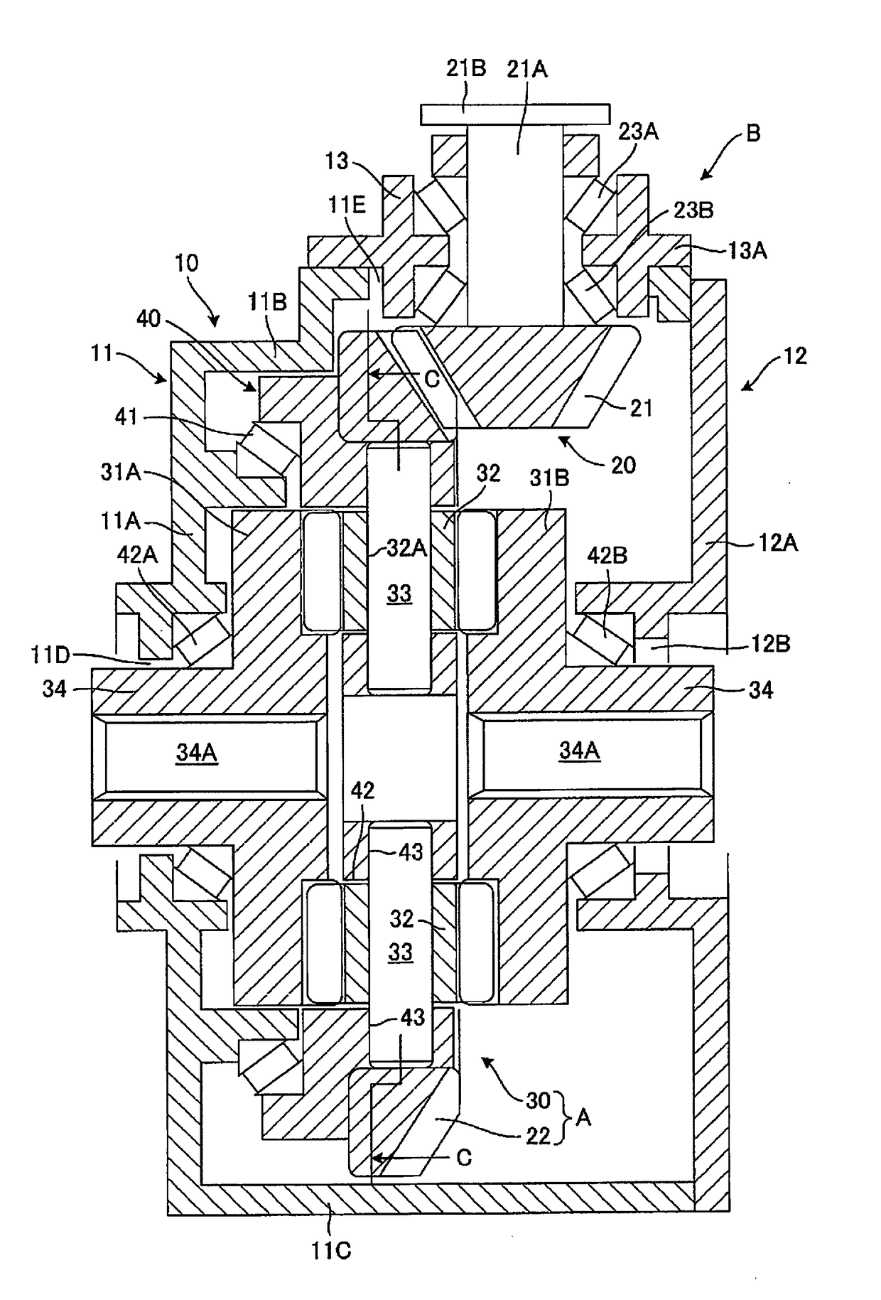
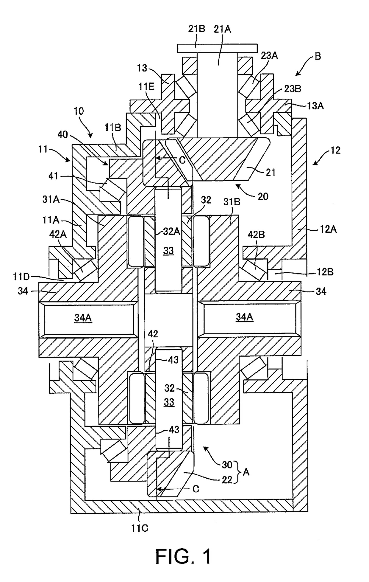
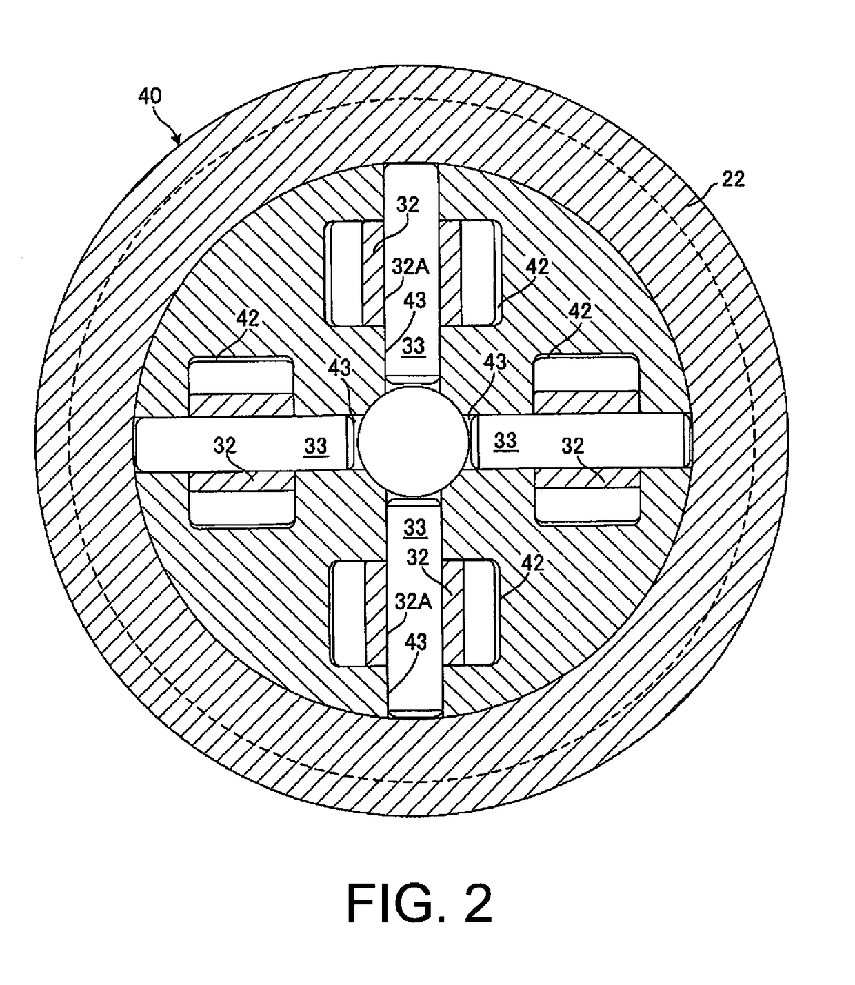
A final drive device includes a housing and a final drive gear mechanism. The final drive gear mechanism is provided in the housing, and comprises a drive pinion and a ring gear meshed with the drive pinion and a differential gear mechanism. The differential gear mechanism includes a pinion rotatably supported by a pinion mate shaft, and a pair of side gears meshed with the pinion from both sides in an axle direction. The final drive device has a pinion carrier that is rotated in a direction around the axle integrally with the pinion mate shaft supporting the pinion, and which is secured to the ring gear. The pinion carrier is provided with a pinion housing unit that houses the pinion while permitting the pinion to rotate around its own axis. The side gears are fixedly located relative to the housing while being permitted to rotate around their own axes.

Description

CROSS-REFERENCE TO RELATED APPLICATIONS[0001]This application is a U.S. National stage application of International Application No. PCT / JP2014 / 068638, filed Jul. 11, 2014.BACKGROUND[0002]Field of the Invention[0003]The present invention relates to a final drive unit with a built-in differential gear mechanism mounted on a drive system of a vehicle.[0004]Background Information[0005]A final drive device with a built-in differential gear mechanism used in a drive system of a vehicle is, for example, configured to subject the rotation of a propeller shaft to final deceleration by a final drive gear mechanism, and to output the decelerated propulsion to left and right drive wheels via a differential gear mechanism.[0006]Japanese Unexamined Patent Application Publication No. 2012-530222 discloses a final drive device in which a differential gear mechanism is configured from a plate-like helical face gear and a helical pinion that meshes with the helical face gear, which are disposed in an...

Claims


Application Information

Patent Timeline
IPC IPC(8): F16H48/10F16H48/40
CPCF16H48/10F16H2048/106F16H2048/102F16H48/40
Inventor TANAKA, TETSUMITSUENDOU, JITSUYUKISONOWA, KENICHIYOKOZAWA, MITSUOTAKAKI, KAZUHIROMAKI, TEPPEIKOIDE, MASAKATSU
Owner NISSAN MOTOR CO LTD
Why Eureka
Try Eureka