Terminal

Active Publication Date: 2016-01-07
YAZAKI CORP
View PDF6 Cites 1 Cited by
  • Summary
  • Abstract
  • Description
  • Claims
  • Application Information

AI Technical Summary

Benefits of technology

The patent is about a new terminal design that reduces electrical resistance and improves performance. By using a stabilizer reinforcing section and engagement section, and separating parts through slits without forming holes, the size of the terminal can be made smaller. This allows for a smaller electrical resistance and improved performance.

Problems solved by technology

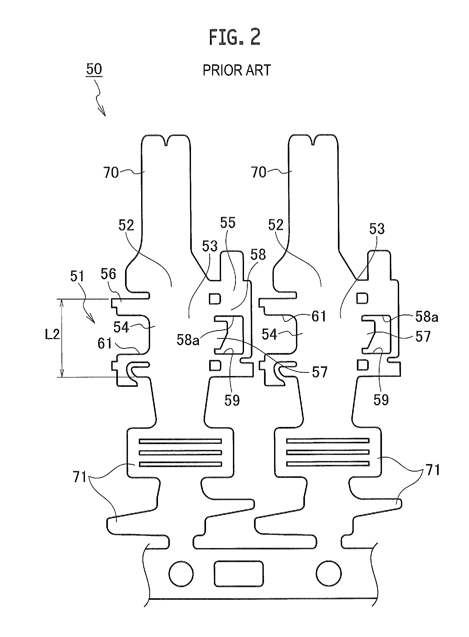
Therefore, the dimension L2 of the body part 51 becomes long and there is a problem that the body part 51 cannot be downsized.
This makes an electric resistance of the male terminal 50 large, and it becomes a cause of deteriorating the electrical performance of the male terminal 50.

Method used


Image

  • Terminal
  • Terminal
  • Terminal

Examples


Embodiment Construction

[0024]Hereinafter, a terminal according to an embodiment of the present application will be explained by referring to FIGS. 3 to 9.

[0025]As illustrated in FIGS. 3 to 6 and 9, a male terminal 1 as the terminal according to the embodiment is formed by folding a conductive metal plate of a predetermined shape (see FIG. 3B and 9). That is, the male terminal 1 is formed for example by forming a plate of a predetermined shape (intermediate body 81) by punching a flat metal material having constant thickness, and thereafter applying predetermined bending.

[0026]The male terminal 1 includes a box-shaped body part 2, a terminal contact part 20 which is provided on the front side of the body part 2 via a first tapered coupling part 19, and an electric wire connecting part 30 which is provided on the rear side of the body part 2 via a second tapered coupling part 29.

[0027]The terminal contact part 20 has a tab shape. The terminal contact part 20 is formed by folding along line “a” of FIG. 3B su...


PUM


Abstract

A terminal is formed by bending a plate of electrically conductive metal and is received in a connector housing. The terminal includes a box-shaped body part, a terminal contact part provided on a front side of the body part, and an electrical wire connecting part provided on a rear side of the body part. When the plate before bending is viewed from the thickness direction, a conductor section having a cross-section having constant width and thickness extends from the terminal contact part to the electrical wire connecting part.

Description

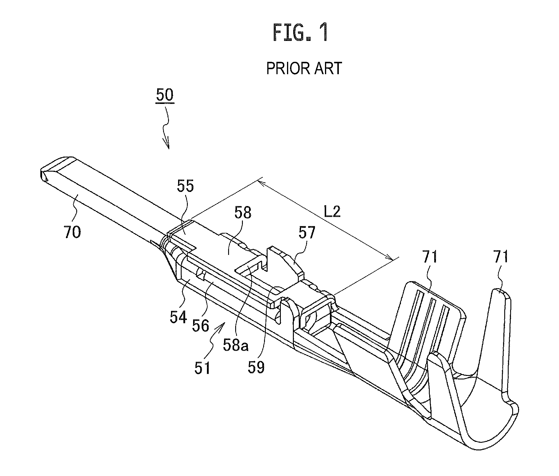
CROSS REFERENCE TO RELATED APPLICATIONS[0001]This application is a continuation of International Application No. PCT / JP2014 / 056931, filed Mar. 14, 2014, and based upon and claims the benefit of priority from Japanese Patent Application No. 2013-057758, filed Mar. 21, 2013, the entire contents of all of which are incorporated herein by reference.TECHNICAL FIELD[0002]The present application relates to a terminal housed in a connector housing.BACKGROUND[0003]As a conventional terminal of this kind, there is one disclosed in JP 2008-153074 A (PTL 1). As illustrated in FIGS. 1 and 2, a male terminal 50 as a conventional terminal is formed by bending a conductive metal plate of a predetermined shape. The male terminal 50 includes a box-shaped body part 51, a terminal contact part 70 provided on a front side of the body part 51, and an electric wire connecting part 71 provided on a rear side of the body part 51.[0004]The body part 51 includes a bottom wall 52, a pair of a first side wall 5...

Claims


Application Information

Patent Timeline
IPC IPC(8): H01R4/18H01R13/422H01R13/436
CPCH01R4/184H01R13/4226H01R13/4362H01R4/185H01R13/422H01R13/04
Inventor MATSUMURA, KAORUFUKAYA, TOMOYOSHIKAJIKAWA, KENJI
Owner YAZAKI CORP
Why Eureka
Try Eureka