Electro-optical device and electronic apparatus
a technology of optical devices and electronic devices, applied in the field of optical devices, can solve the problems of increased size of electro-optic devices, wasteful use, and higher probability of short-circuiting between both substrates, and achieve the effect of reducing distance, reducing spacing, and ensuring reliability in the electrical conduction region between both substrates
- Summary
- Abstract
- Description
- Claims
- Application Information
AI Technical Summary
Benefits of technology
Problems solved by technology
Method used
Image
Examples
embodiment 1
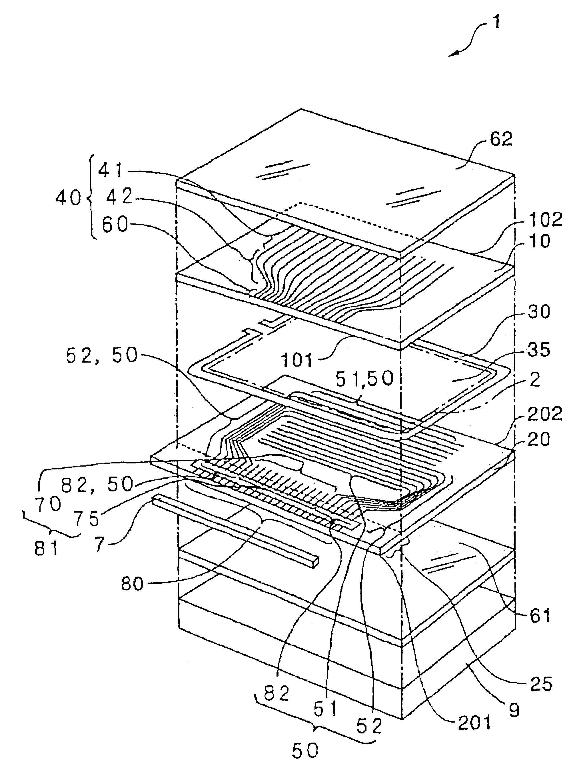
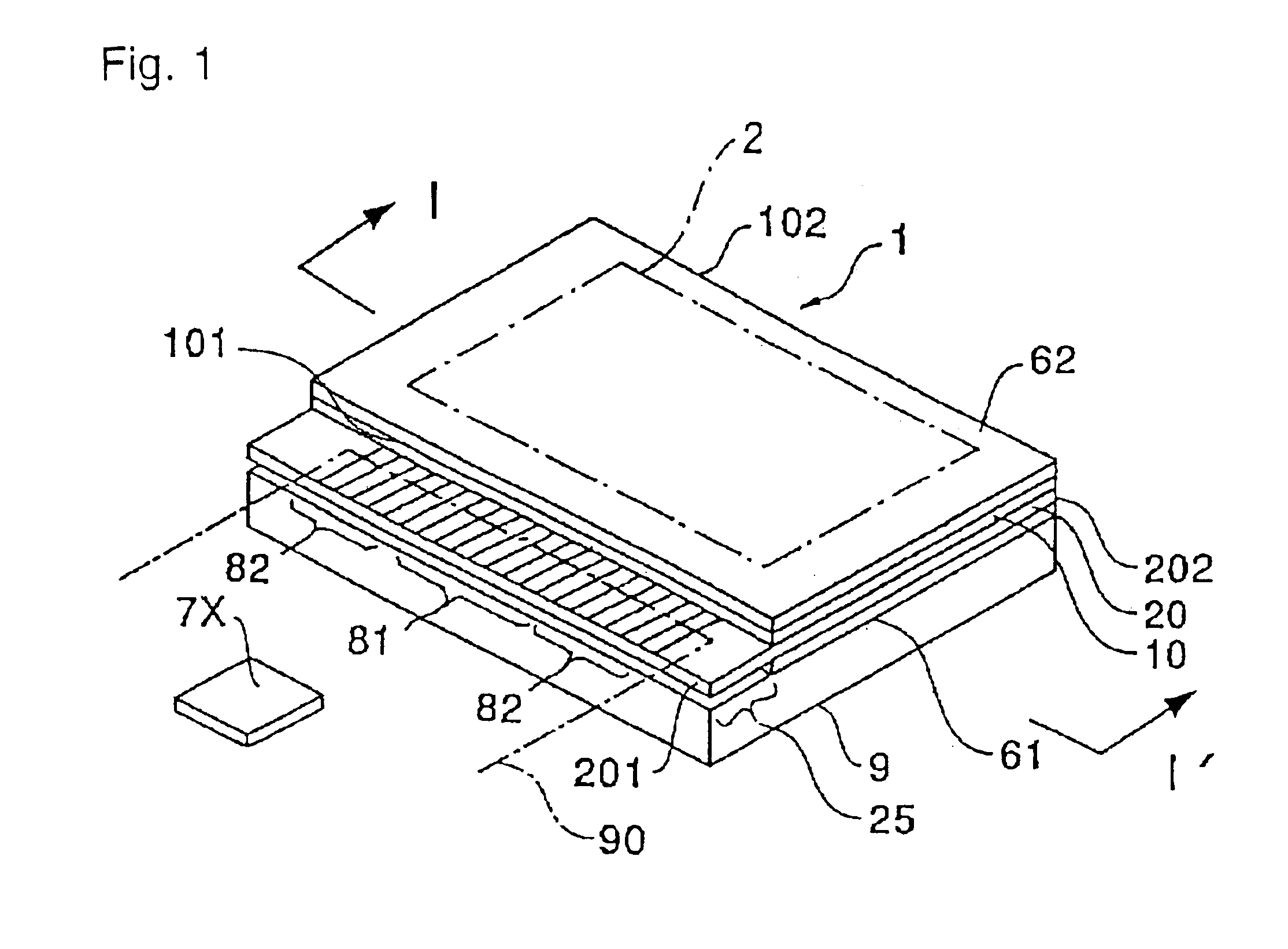
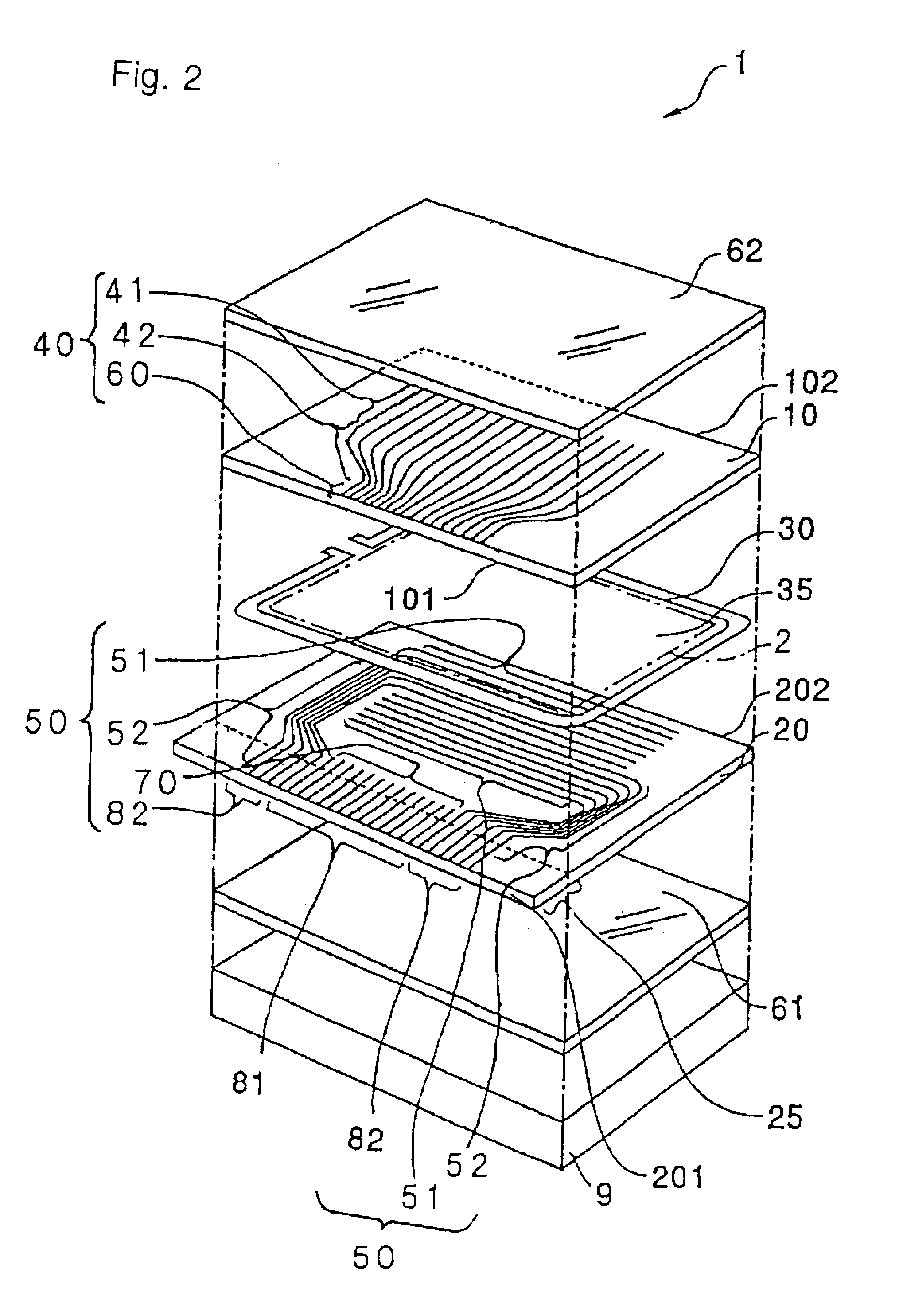
[0103]On the first transparent substrate 10, as with Embodiment 1 described above by referring to FIG. 3, sets of color filters 7R, 7G and 7B of red (R), green (G) and blue (B) are formed in areas corresponding to points at which the first electrodes 40 intersect the second electrodes 50. An insulating flattening film 11, the first electrodes 40 and an alignment film 12 are formed in this order on the surface side of the color filters 7R, 7G and 7B. On the second transparent substrate 20, the second electrodes 50 and an alignment film 22 are formed in this order.
[0104]In the electro-optic device 1, the first electrodes 40 are formed of an ITO film (transparent conductive film). On the other hand, the second electrodes 50 are formed of a metallic film (conductive film) capable of reflecting light, such as an aluminum film, an alloy film made of primarily aluminum, a silver film, or a silver alloy film made of primarily silver.
[0105]Also, in the electro-optic device 1 of this embodime...
embodiment 2
[0154]In Embodiment 2 described above, the second electrodes 50 comprises the drive portions 51 extending straight over the image display area 2, and the wiring portions 52 routed from the drive portions 51 up to the area in which the driving IC 7 is mounted, the wiring portions 52 being formed on both outer sides of the first terminals 81 in the direction of width of the second transparent substrate 20. However, the terminal arrangement may be modified such that the second electrodes 50 may be routed from the area, in which the driving IC 7 is mounted, to pass through only one side outward of the first terminals 81 in the direction of width of the second transparent substrate 20, and may be then extended from that one side to the image display area 2.
embodiment 3
[0155]FIGS. 13 and 14 are respectively a perspective view showing the construction of an electro-optic device 1 of the present invention, and an exploded perspective view of the electro-optic device 1.
[0156]As shown in FIGS. 13 and 14, the electro-optic device 1 of this embodiment comprises a first transparent substrate 10 and a second transparent substrate 20 arranged in an opposed relation, a sealing member 30 applied in the form of a rectangular frame for bonding both the substrates to each other, and a liquid crystal layer 4 sealed in a liquid crystal sealed-in space 35 surrounded by the first transparent substrate 10, the second transparent substrate 20, and the sealing member 30. Of the liquid crystal sealed-in space 35, an area in which later-described pixels are arrayed in a matrix pattern serves as an image display area 2.
[0157]The first transparent substrate 10 and the second transparent substrate 20 are each a plate-like member made of quartz, glass, plastic or the like....
PUM
| Property | Measurement | Unit |
|---|---|---|
| electric field | aaaaa | aaaaa |
| electrical resistance | aaaaa | aaaaa |
| electrically conducting | aaaaa | aaaaa |
Abstract
Description
Claims
Application Information
 - R&D
- Intellectual Property
- Life Sciences
- Materials
- Tech Scout
- Unparalleled Data Quality
- Higher Quality Content
- 60% Fewer Hallucinations
Browse by: Latest US Patents, China's latest patents, Technical Efficacy Thesaurus, Application Domain, Technology Topic, Popular Technical Reports.
© 2025 PatSnap. All rights reserved.Legal|Privacy policy|Modern Slavery Act Transparency Statement|Sitemap|About US| Contact US: help@patsnap.com


