Slow Blow Fuse and Electric Junction Box

Inactive Publication Date: 2009-03-12
SUMITOMO WIRING SYST LTD
View PDF29 Cites 5 Cited by
  • Summary
  • Abstract
  • Description
  • Claims
  • Application Information

AI Technical Summary

Benefits of technology

[0031]As described above, according to the present invention, the coupling part of the fuse element is projected orthogonally to the direction in which the mating terminals are inserted into the female terminal parts respectively. Therefore it is possible to shorten the dimension of the female terminal parts in the direction in which the mating terminals are inserted thereinto respectively and thus make the height of the slow blow fuse low.
[0032]The female terminal parts of the fuse element are so configured that the mating terminals can be inserted thereinto from both ends in the terminal plugging direction, and the housing accommodating the fuse element is provided with the insertion ports confronting the plugging ports of the female terminal parts disposed at the vertical upper and lower ends thereof. Therefore it is possible to insert the mating terminals to be connected with the female terminal parts respectively into the female terminal parts respectively in two opposite directions.
[0033]In equipment for inserting the slow blow fuse into the fuse accommodation portion of the electric junction box, it is possible to simplify the construction of an apparatus for regulating the posture of the slow blow fuse and hence decrease the cost.

Problems solved by technology

Thus it is necessary to use a dedicated equipment to do so, which makes the production cost high.

Method used


Image

  • Slow Blow Fuse and Electric Junction Box
  • Slow Blow Fuse and Electric Junction Box
  • Slow Blow Fuse and Electric Junction Box

Examples


first embodiment

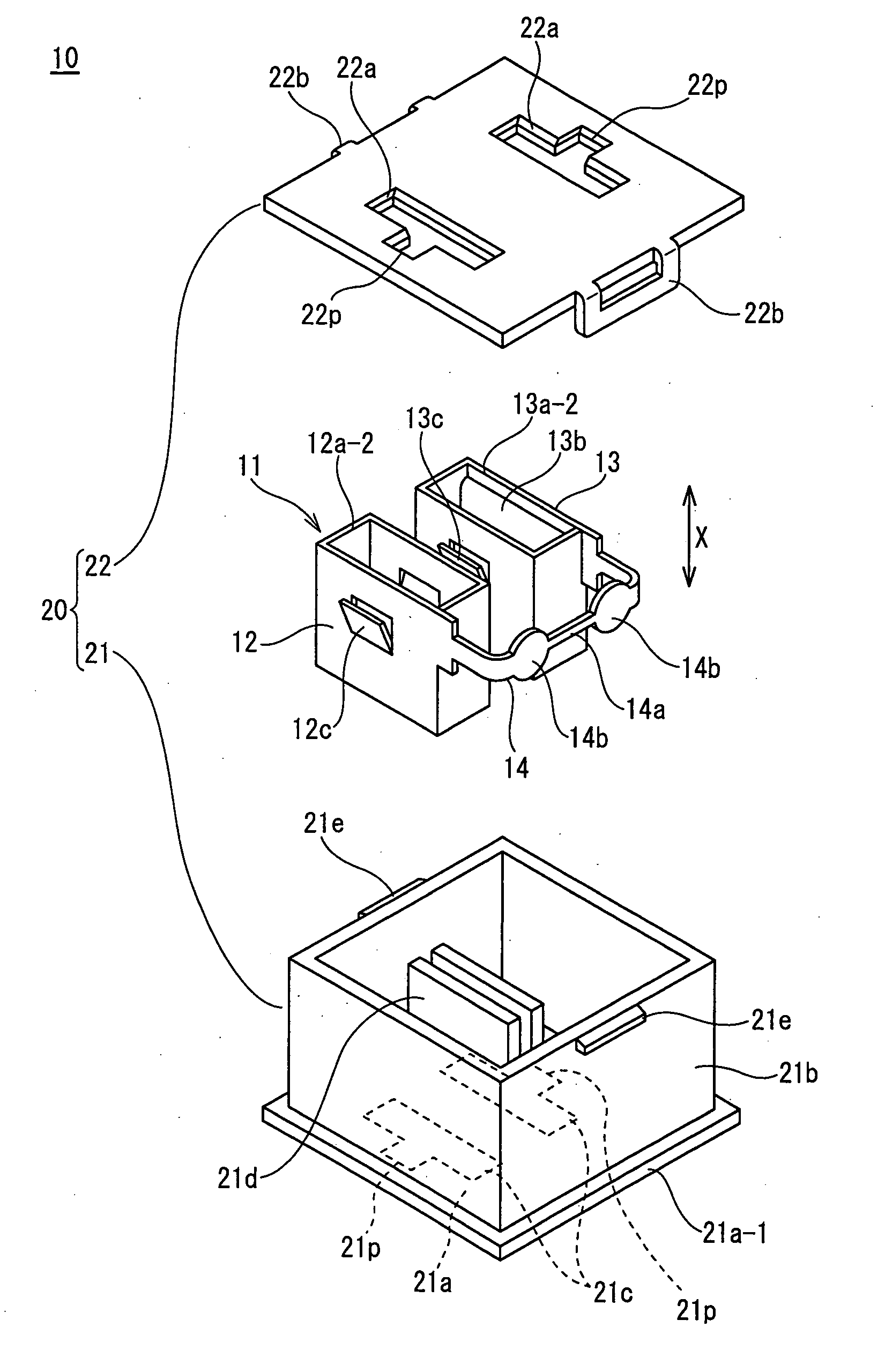
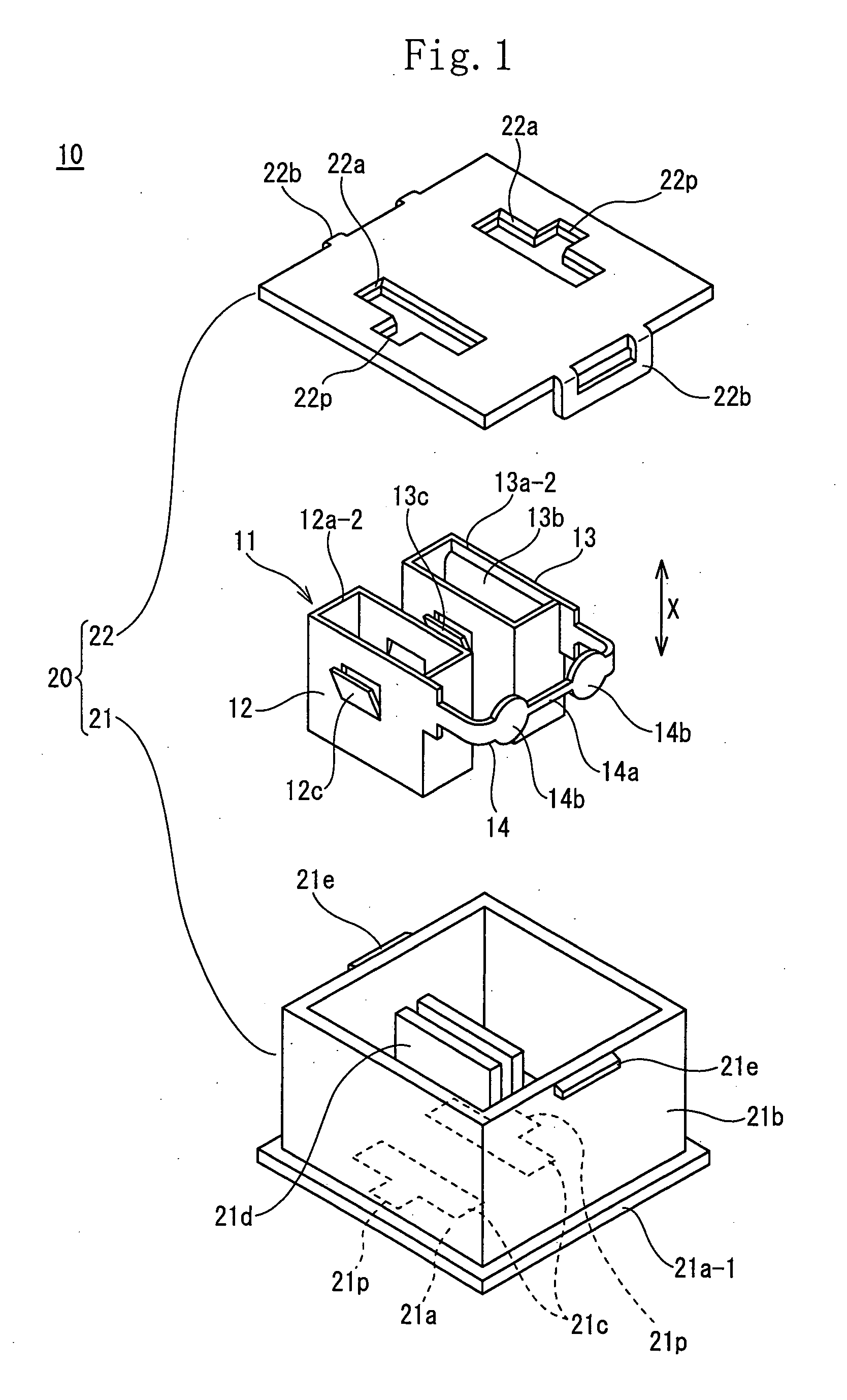
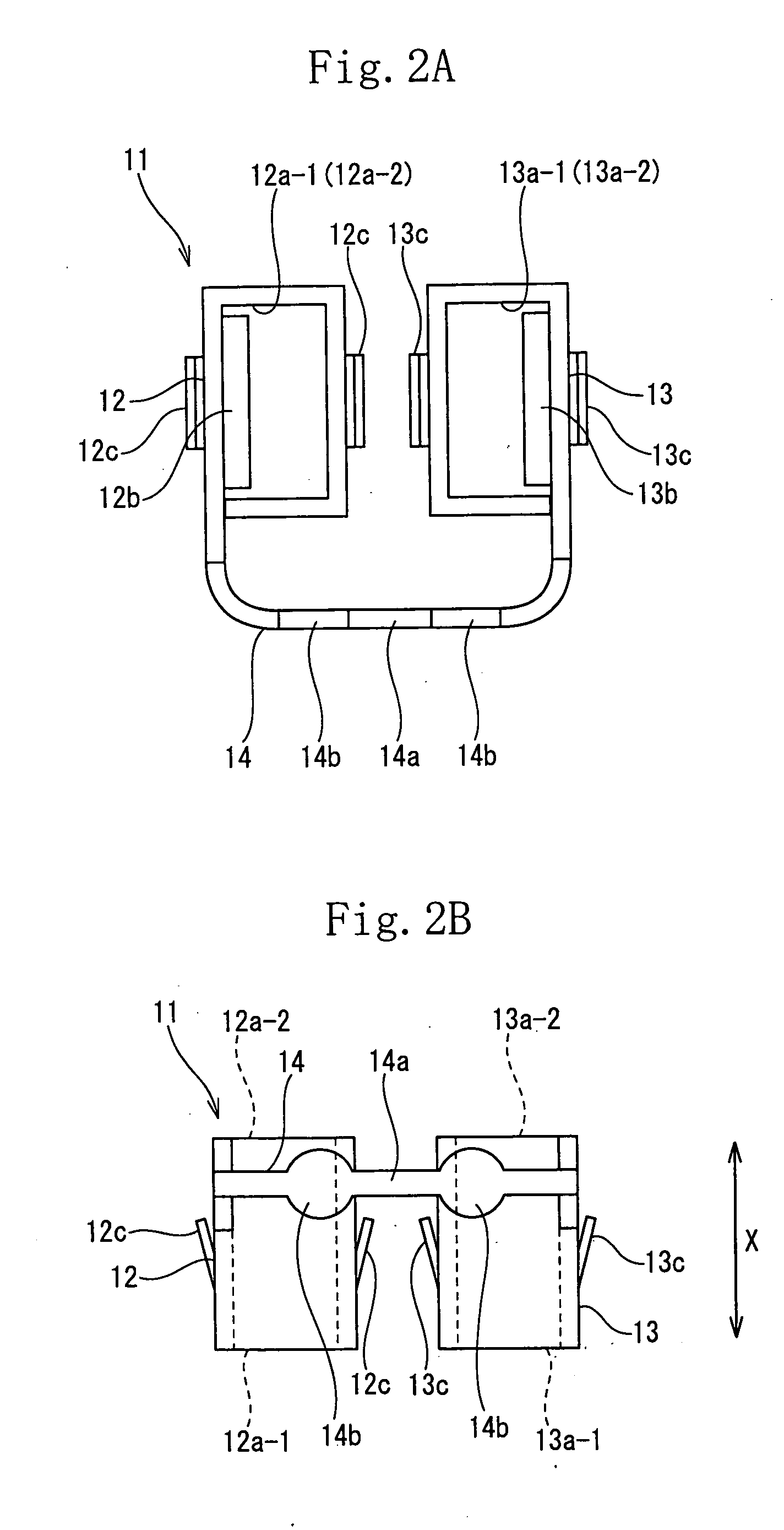
[0069]FIGS. 1 through 5 show the present invention. A slow blow fuse 10 includes a fuse element 11 having a pair of female terminal-shaped input and output terminal parts 12, 13 continuous with each other by a coupling part 14 having a fusing portion 14a; and a box-shaped housing 20, made of an insulating resin, which accommodates the fuse element 11.

[0070]The fuse element 11 is formed by punching a conductive metal plate into a required configuration and thereafter bending an obtained metal piece. The input terminal part 12 of the fuse element 11 and the output terminal part 13 thereof are so disposed that plugging directions of mating terminals to be connected thereto are parallel with each other. Plugging ports 12a-1, 12a-2, 13a-1, and 13a-2 through which the mating terminals are inserted thereinto are formed at upper and lower ends of the input terminal part 12 and the output terminal part 13 in the terminal plugging direction so that the mating terminals can be inserted therein...

second embodiment

[0095]FIGS. 7 through 9 show the present invention.

[0096]The slow blow fuse 10 of the second embodiment is connected with an internal circuit of the electric junction box 40 with the slow blow fuse 10 accommodated in the fuse accommodation portion 45 of the electric junction box 40.

[0097]As shown in FIG. 7, a convex portion 23 having a predetermined configuration is formed on an outer wall surface of the housing 20 through which the insertion ports 21c, 22a are formed. In one slow blow fuse 10, the convex portion 23 formed on the bottom wall 21a of the main body 21 and the convex portion 23 formed on the cover 22 have the same configuration and are formed at symmetrical positions.

[0098]A slow blow fuse 10′ having a capacity different from that of the slow blow fuse 10 is provided with a convex portion having a configuration different from that of the slow blow fuse 10. In the slow blow fuse 10′, the convex portions are also formed at symmetrical positions.

[0099]In the electric junct...


PUM


Abstract

A fuse element comprises a pair of female terminal portions into which the other pair of terminals are plugged and which are disposed in parallel and a blowout portion for coupling the pair of female terminal portions in a direction perpendicular to the direction in which the other pair of terminals are plugged. A slow blow fuse comprising the fuse element houses the fuse element in an insulating-resin housing and is provided with an insertion port in which the other pair of terminals are plugged into the pair of female terminal portions in the opposed surface of the housing.

Description

TECHNICAL FIELD[0001]The present invention relates to a fuse element of a slow blow fuse, the slow blow fuse, and an electric junction box and more particularly the present invention is intended to decrease the height of the fuse element and that of the slow blow fuse having the fuse element and facilitate a work of mounting the slow blow fuse in the electric junction box.BACKGROUND ART[0002]Conventionally to protect a circuit from eddy current, a fuse is mounted on the electric junction box for distributing a power supply to electric component parts mounted on a car. As disclosed in Japanese Patent Application Laid-Open No. 2004-281078 (patent document 1), the slow blow fuse 1 shown in FIG. 11 is proposed.[0003]In the slow blow fuse 1, the fuse element 5 having the female terminal-shaped input terminal part 2 and the output terminal part 3 connected thereto by the coupling part 4 having the fusing portion 4a is accommodated inside the box-shaped housing 6 made of an insulating resi...

Claims


Application Information

Patent Timeline
IPC IPC(8): H01H85/041H01H85/045H01H85/147H01H85/175H01H85/24H01H85/50H01R13/68H01R13/688
CPCH01H85/0417H01H85/08H01H2085/208H01H85/24H01H85/22
Inventor MIYAMOTO, TAKASHI
Owner SUMITOMO WIRING SYST LTD
Why Eureka
Try Eureka