Vapor collection and treatment of off-gas from an in-situ thermal desorption soil remediation system

a technology of thermal desorption soil and vapor collection system, which is applied in the field of soil remediation, can solve the problems of high cost of methods, high capital cost, and inability to meet the needs of the public, and achieve the effect of reducing capital cost, transportation cost and operating expenses

Inactive Publication Date: 2005-05-26
BOARD OF RGT THE UNIV OF TEXAS SYST
View PDF1 Cites 12 Cited by
  • Summary
  • Abstract
  • Description
  • Claims
  • Application Information

AI Technical Summary

Benefits of technology

[0047] The treatment facility does not require the use of a thermal oxidizer as did previous treatment facilities. Removing the thermal oxidizer from the treatment facility eliminates the large capital cost, transportation costs, and operating expenses associated with the thermal oxidizer. The elimination of the thermal oxidizer may allow the soil remediation process to be run unattended. A site supervisor may periodically check the system and perform normal maintenance functions at the site to ensure proper operation of the soil remediation system. Continuous manned operation of the in situ soil remediation process may not be required.

Problems solved by technology

Subsurface soil may become contaminated with chemical, biological, and / or radioactive contaminants.
Contaminants in subsurface soil can become public health hazards if the contaminants migrate into aquifers, into air, or into the food supply.
Although these methods may be successfully applied in some applications, the methods can be very expensive.
The methods may not be practical if many tons of soil must be treated.
Off-gas removed from the soil by the vacuum may include contaminants that were within the soil.
The permeability of the subsurface soil may limit the effectiveness of a SVE process.
These methods may not be effective methods of opening the pores of the soil to admit airflow.
Lowering the water table may result in moist soil.
Air conductivity through moist soil is limited.
A vacuum dewatering technique may have practical limitations.
The vacuum generated during a vacuum dewatering technique may diminish rapidly with distance from the dewatering wells.
The use of a vacuum dewatering technique may not result in a significant improvement to the soil water retention problem.
Air and vapor may be impeded from flowing through other regions of heterogeneous soil.
Air and vapor may be impeded from flowing through overly compacted fill material.
Buried debris within fill material may also impede air flow through subsurface soil.
The heat added to the contaminated soil may raise the temperature of the soil above the vaporization temperatures of the soil contaminants.
The resulting water vapor may volatize contaminants within the soil by steam distillation.
Steam distillation within the soil may result in the removal of medium and high boiling point contaminants from the soil.
In addition to allowing greater removal of contaminants from the soil, the increased heat of the soil may result in the destruction of contaminants in situ.
The presence of an oxidizer, such as air, may result in the oxidation of the contaminants that pass through soil that is heated to high temperatures.
Heating the subsurface soil may result in an increase in the permeability of the soil.
A heater / suction well may cost about $240 per foot to produce.
Often the condition of the wells after removal is poor.
The wells may be corroded and / or bent.
Setting up the vapor collection piping constitutes a large part of the field installation cost of an ISTD soil remediation process.
A high soil temperature may destroy most of the soil contaminants before the contaminants are drawn to the surface facilities.
Thermal oxidizers are costly to purchase, set up, and operate.
The capital expense of a vapor treatment system described above is very high (more than one million dollars).
Thermal oxidizers may be large and heavy units that are expensive to mobilize.
An ISTD soil remediation process may require a large amount of computerized instrumentation for thermal well control and temperature monitoring.
Thermocouples and control wiring for the thermal wells are extensive and laborious to install, connect, and troubleshoot.
Thus, there may only be a small net acceleration of the heating process due to heating rate control.
Moreover, the well controllers increase the chance of heater failure because they are controlling temperature at a single thermocouple location.
If the thermocouple is not located at the hottest portion of a heater, the hottest portion of the heater may be maintained at an excessively hot temperature that could cause the heating element to fail.
Long unheated sections of a strip heater may be needed for deep soil contamination that is not near the soil surface.
Passing the off-gas through the high temperature zone may result in the thermal degradation of contaminants within the off-gas.
Also, horizontally positioned strip heaters may be very long.
The heater section of a strip heater and the power source are designed to supply heat input into the soil that is greater than the heat input that the soil can absorb, but not enough to overheat the strip heater.
The power source provides a substantially constant voltage to the strip heaters, so an increase in the resistance of a strip heater decreases the power dissipation of the strip heater.
The application of a steady voltage to a series of heater strips may result in steady state power dissipation through the strip heaters.

Method used


Image

  • Vapor collection and treatment of off-gas from an in-situ thermal desorption soil remediation system
  • Vapor collection and treatment of off-gas from an in-situ thermal desorption soil remediation system
  • Vapor collection and treatment of off-gas from an in-situ thermal desorption soil remediation system

Examples


Embodiment Construction

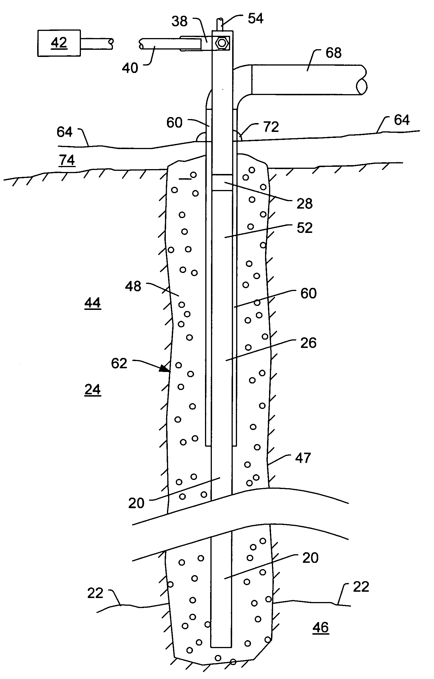
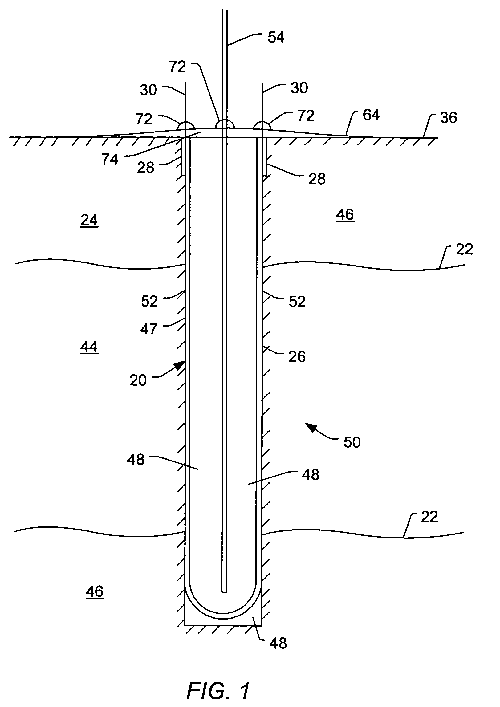
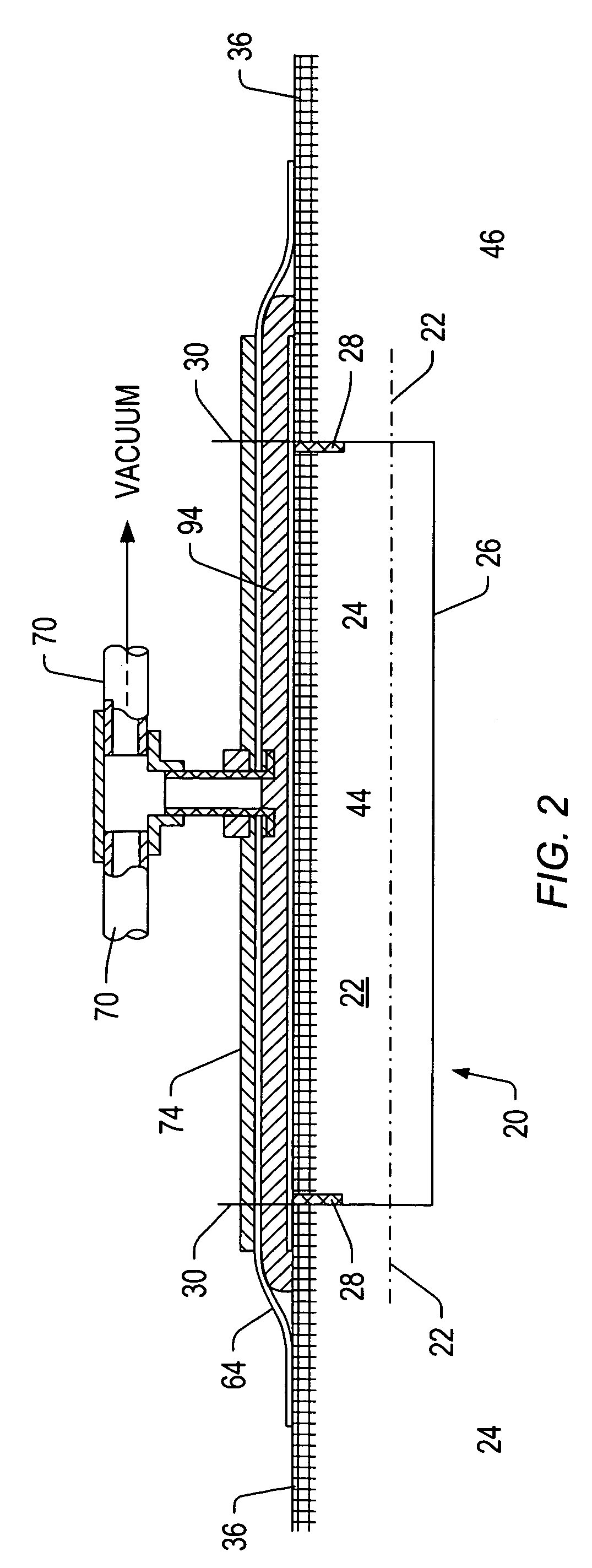
[0065] As depicted in FIG. 1, an in situ thermal desorption soil remediation process may use strip heaters 20 to conductively apply heat to contaminated region 22 of soil 24. The soil remediation process may be used to remove contaminants from the soil 24. A vacuum may be applied to the soil 24 along with conductive heat to remove contaminants from the soil. FIG. 1 shows an embodiment of a strip heater 20 vertically positioned in contaminated soil 24. FIG. 2 shows an embodiment of a strip heater 20 horizontally positioned in soil 24. Strip heaters 20 may also be inserted in soil 24 in non-vertical and non-horizontal (e.g., angled) orientations.

[0066] A strip heater 20 may include heater section 26, transition sections 28, and pins 30. The heater section 26 may be formed of a high temperature, chemical resistant metal. The heater section 26 may be formed of a stainless steel, including but not limited to type 304 stainless steel, type 309 stainless steel, type 310 stainless steel, o...


PUM


Abstract

An in situ thermal desorption system may be used to remove contamination from soil. Off-gas removed from the soil may be transported from the soil to a treatment facility by high temperature hoses and plastic piping. The use of high temperature hose and plastic pipe may reduce the capital cost, installation cost, and operating cost as compared to conventional transport systems from thermal desorption soil remediation systems. The high temperature hose and plastic pipe are highly resistant to corrosion caused by the off-gas. The treatment facility may separate the off-gas into a liquid stream and a vapor stream. The liquid stream and the vapor stream may be processed to reduce contaminants within the liquid stream and vapor stream to acceptable levels.

Description

PRIORITY CLAIM [0001] This application is a divisional application of U.S. patent application Ser. No. 09 / 549,902 entitled “Vapor Collection And Treatment Of Off-gas From An In-situ Thermal Desorption Soil Remediation System,” filed Apr. 14, 2000.BACKGROUND [0002] 1. Field of the Invention [0003] The present invention relates generally to soil remediation, and more particularly to a vapor collection system and treatment facility for off-gas from an in situ thermal desorption soil remediation process. [0004] 2. Description of Related Art [0005] Contamination of subsurface soils has become a matter of great concern in many locations. Subsurface soil may become contaminated with chemical, biological, and / or radioactive contaminants. Contamination of subsurface soil may occur in a variety of ways. Hazardous material spills, leaking storage vessels, and landfill seepage of improperly disposed of materials are just a few examples of the many ways in which soil may become contaminated. Con...

Claims


Application Information

Patent Timeline
Patent Type & Authority Applications(United States)
IPC IPC(8): B09C1/06E21B36/04H05B3/00H05B3/03
CPCB09C1/062B09C2101/00H05B3/03H05B3/0004E21B36/04
Inventor VINEGAR, HAROLD J.STEGEMEIER, GEORGE L.
Owner BOARD OF RGT THE UNIV OF TEXAS SYST
Why Eureka
Try Eureka