Gas sensor, especially a lambda probe

a technology of gas sensors and probes, applied in the field of gas sensors, can solve problems such as harmful nitrogen oxide production

Inactive Publication Date: 2003-01-30
ROBERT BOSCH GMBH
View PDF0 Cites 4 Cited by
  • Summary
  • Abstract
  • Description
  • Claims
  • Application Information

AI Technical Summary

Problems solved by technology

However, during combustion using an oxygen excess, harmful nitrogen oxides are produced that may only be absorbed for a limited time by so-called adsorption catalysts in the exhaust branch of the motor vehicle.

Method used


Image

  • Gas sensor, especially a lambda probe
  • Gas sensor, especially a lambda probe
  • Gas sensor, especially a lambda probe

Examples


Embodiment Construction

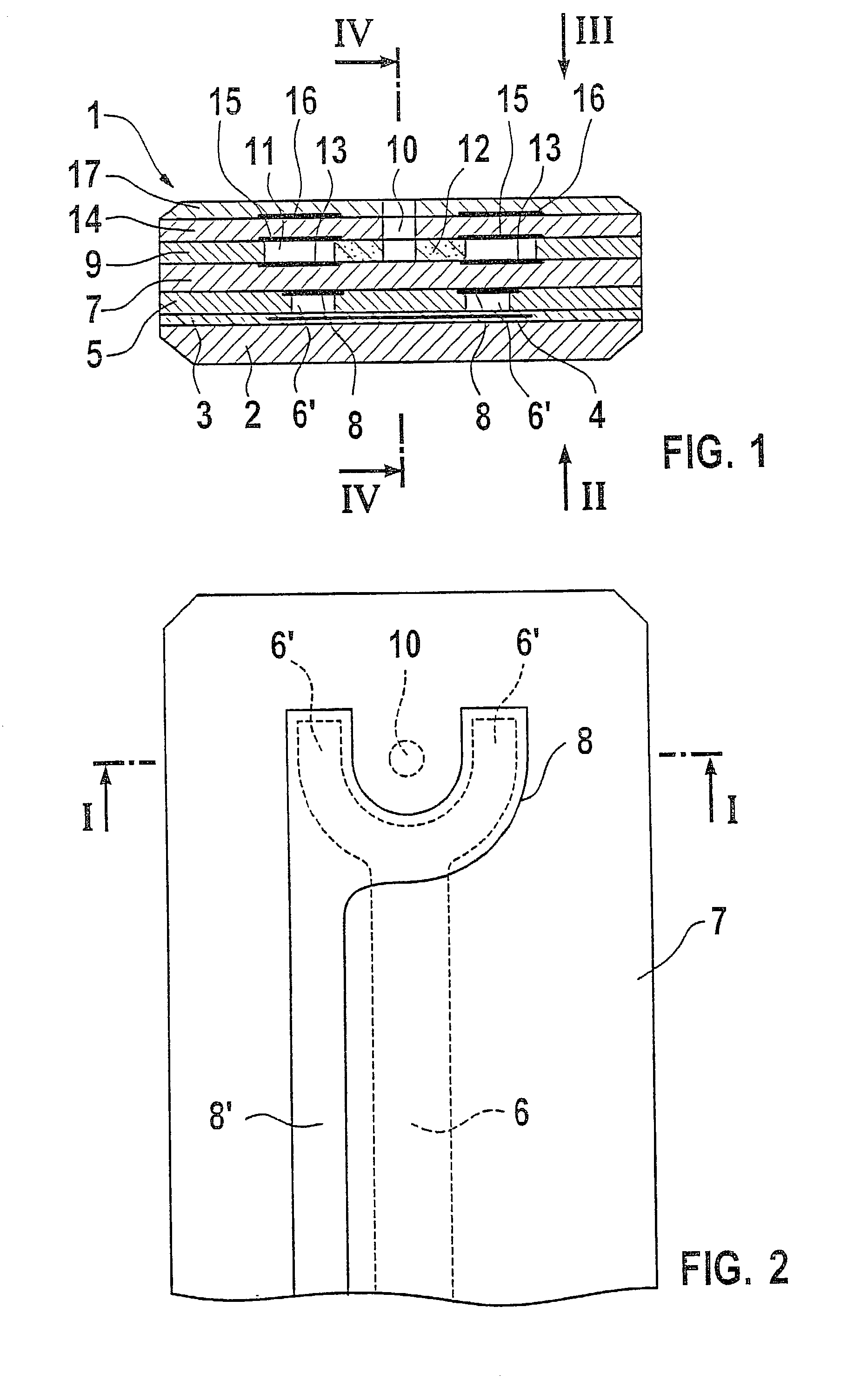
[0025] According to FIG. 1, the represented lambda probe has a body 1, which is formed as a ceramic laminate. The layers of the laminate are placed or deposited on one another in the green condition. Subsequent sintering, which may be carried out after or during simultaneous pressing of the laminate, produces a hard ceramic body 1.

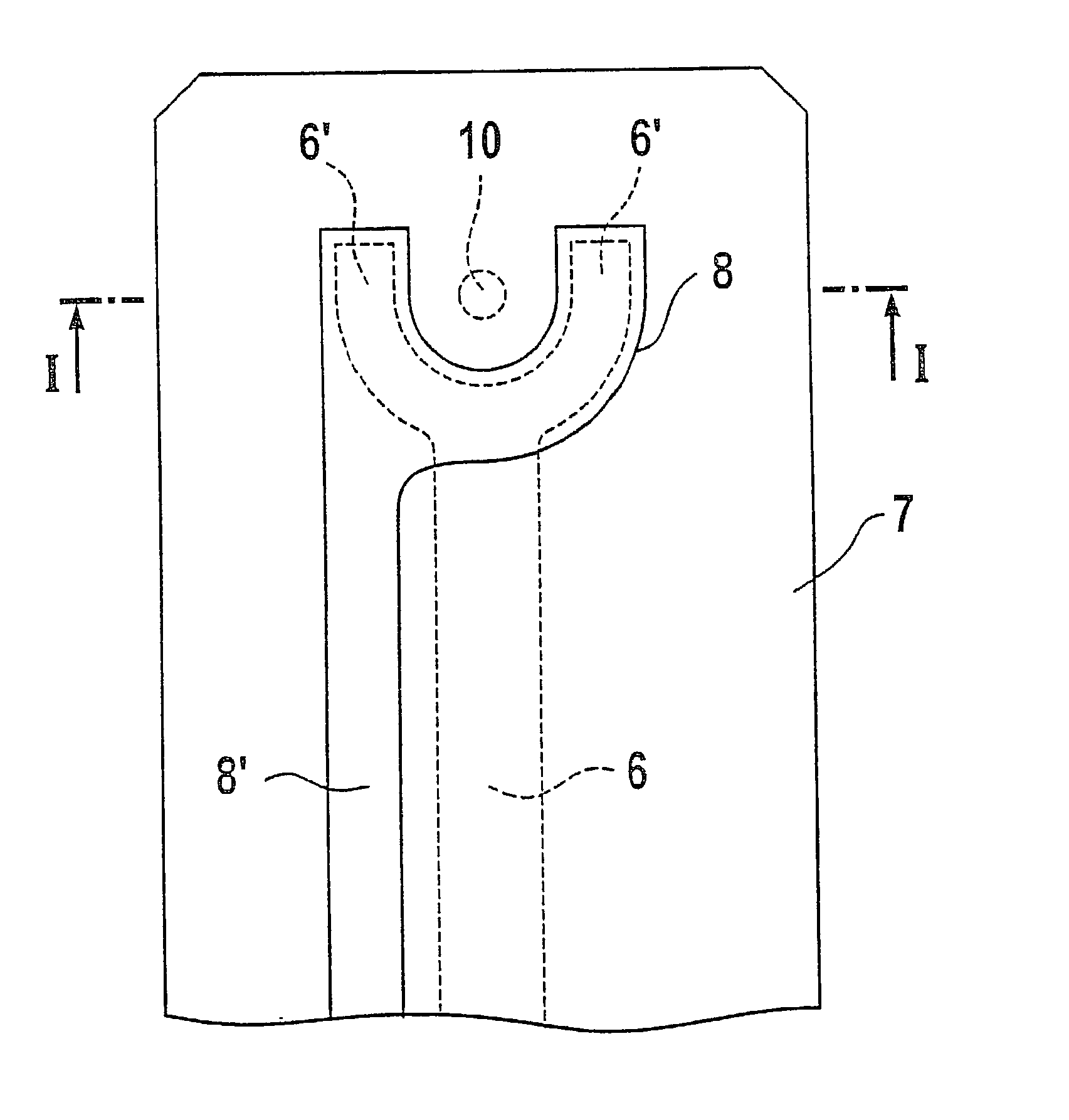
[0026] In the example in FIG. 1, a bottom layer 2 is provided in the form of a thicker film of zirconium oxide. Above this is an electrically insulating double layer 3, in which an electrical resistance heater 4 as well as corresponding printed circuit traces for electrical current supply are embedded. Above that lies layer 5, which is produced and patterned by screen printing and is made, for example, of a zirconium oxide paste. Recessed within this layer is a reference air duct 6, whose base plan is shown by way of example in FIG. 2 and is explained in greater detail below. As shown, this reference air duct 6 may have two end regions 6', which communicat...


PUM

PropertyMeasurementUnit
permeableaaaaaaaaaa
areaaaaaaaaaaa
electrical conductivityaaaaaaaaaa

Abstract

To improve the electrical properties of the gas sensor, the following measures may be used: In the top view of the layer planes of the body of the sensor, printed circuit traces for electrodes are situated outside of cavities in the body, in particular outside of the reference air duct. The electrodes are enlarged in the direction of the exhaust-side end of the sensor. The printed circuit traces have an increased layer thickness or are formed as a double layer.

Description

BACKGROUND INFORMATION[0001] The present invention relates to gas sensors, in particular lambda probes, having a body formed as a sintered ceramic laminate and a reference air duct situated therein within a layer of the laminate, an electrical resistance heater being provided on its one side and an electrode configuration being provided on its other side, the electrode configuration having at least one reference electrode that is situated on the inside of a boundary wall of the reference air duct and is permeable for gases at least regionally and that has a Nernst electrode that is acted upon by gases to be sensed, the Nernst electrode also being at least regionally permeable for gases and being separate from the reference electrode by a solid electrolyte layer that is conductive and permeable for ions, oxygen ions in particular, and the electrodes being connected to printed circuit traces that essentially extend in the direction of the reference air duct.[0002] Today, exhaust syste...

Claims


Application Information

Patent Timeline
Patent Type & Authority Applications(United States)
IPC IPC(8): G01N27/419G01N27/407G01N27/417
CPCG01N27/4071
Inventor SCHEER, HEINERRENZ, HANS-JOERGRIEGEL, JOHANNDIEHL, LOTHARTHIEMAN-HANDLER, SABINE
Owner ROBERT BOSCH GMBH
Why Eureka
Try Eureka