

Dual heat to cooling converter
- Summary
- Abstract
- Description
- Claims
- Application Information
AI Technical Summary
Benefits of technology
Problems solved by technology
Method used
Image

Examples
Embodiment Construction
[0024] Creation and operation of structures utilizing the cooling action and electricity action of thermoelectric and thermionic devices are discussed at length in the literature, hereby incorporated by reference.
[0025] The present invention relates to a heat to cooling converter utilizing the thermoelectric or thermionic cooling component and utilizing the thermoelectric or thermionic component. Since both devices appear visually identical, only the thermoelectric devices will be shown fore easier identification.
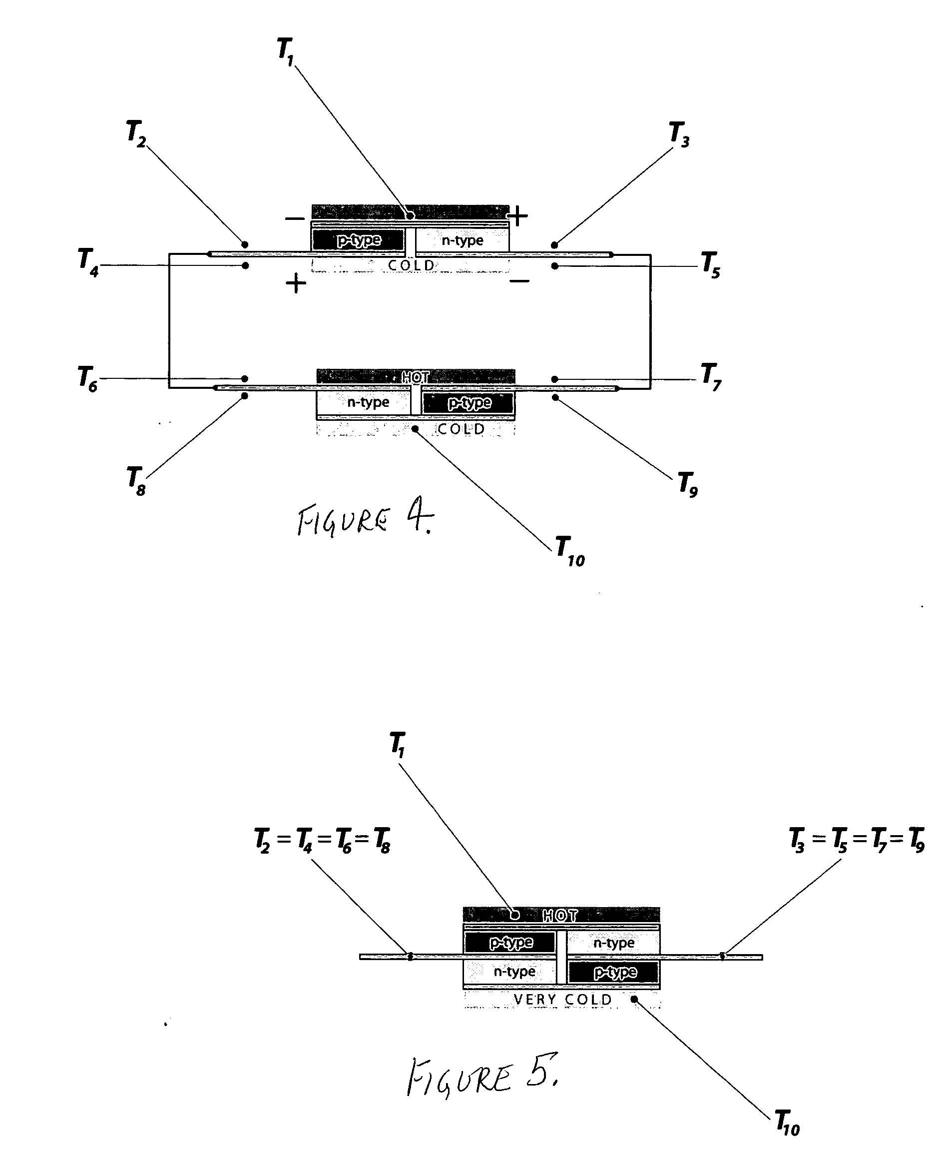
[0026] According to the Peltier Effect, current passed through the device will result in absorption of heat at one end, and emission of heat at the other end. According to Seebeck Effect, a heat applied to one end of the device with constant temperature maintained at the opposite end will produce a voltage across the device, called the Seebeck voltage.
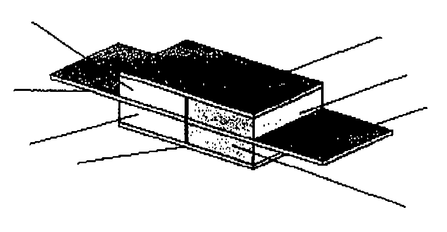
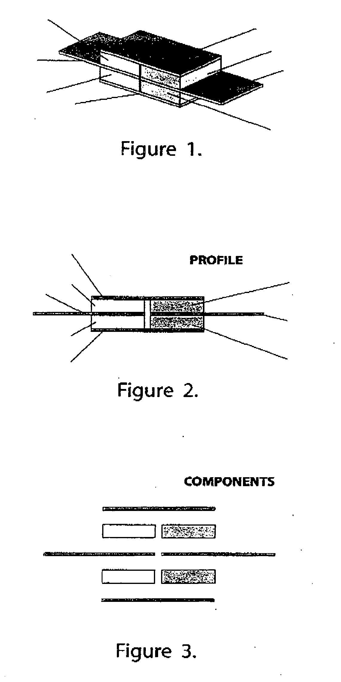
[0027]FIG. 1 shows an example of a device converting heat to cooling. Items 101, 102, 106, 103 and 108 represent in this ...
PUM
 Abstract
Description
Claims
Application Information