
Heat to cooling converter

a converter and heat exchange technology, applied in the field of cooling equipment, can solve the problems of difficult cooling, large-scale thermoelectric generators cannot compete with oil-fired central power stations, and relatively easy to heat up, and achieve the effects of reducing heat loss, reducing heat loss, and reducing heat loss

Inactive Publication Date: 2005-10-27
STRNAD RICHARD J
View PDF6 Cites 27 Cited by
  • Summary
  • Abstract
  • Description
  • Claims
  • Application Information

AI Technical Summary

Benefits of technology

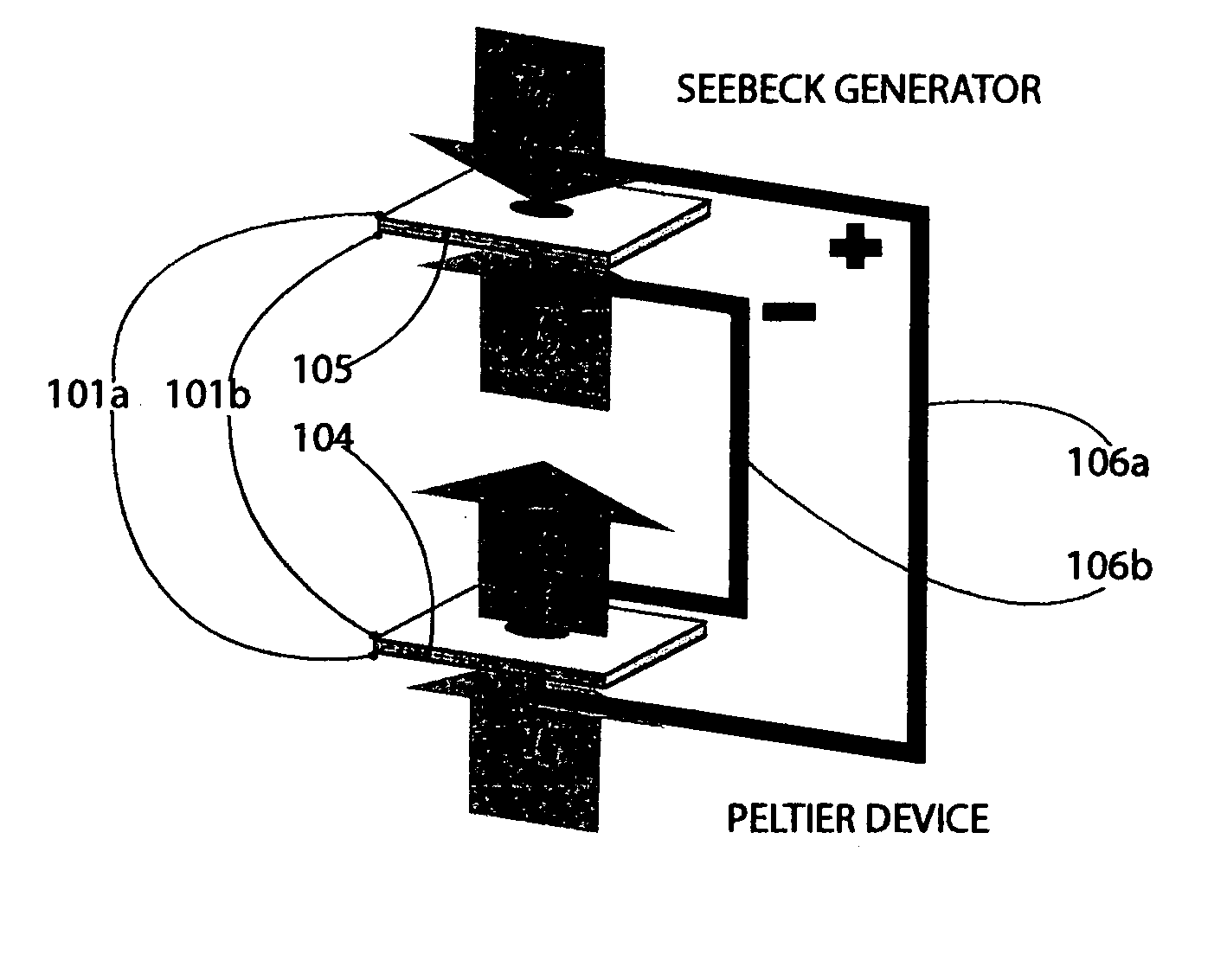
[0012] The present application discloses a new type of cooling device which converts thermal energy directly to cooling. The electricity generator and the cooling device are separated by an adiabatic wall and both devices are in thermal equilibrium with each other. The adiabatic wall also provides electrical connection between the two devices. The small distance between both devices is minimizing the electrical resistance thus guaranteeing maximum power transfer from device to device.
[0015] A further object of the invention is to design the adiabatic wall with smallest electrical resistance and highest heat removal effectiveness. Low electrical resistance is essential to minimize energy transport losses and the contact area of the adiabatic wall with the fluid or gas must be optimized for maximum heat extraction.

Problems solved by technology

Heating is relatively easy to achieve, cooling is more difficult.
Large scale thermoelectric generators cannot compete with oil-fired central power stations, which operate at efficiencies of 35-40%.
Because the two sides are separated by a gap the heat cannot easily flow back.

Method used


Image

  • Heat to cooling converter
  • Heat to cooling converter
  • Heat to cooling converter

Examples


Embodiment Construction

[0027] In the following description of the invention or preferred embodiments, reference is made to the accompanying drawings which form a part hereof, and in which is shown by way of illustration specific embodiments in which the invention may be practiced. These embodiments are described in sufficient detail to enable those skilled in the art to practice the invention, and it is to be understood that other embodiments may be utilized and that logical, mechanical and electrical changes may be made without departing from the spirit of scope of the invention. To avoid detail not necessary to enable those skilled in the art to practice the invention, the description may omit certain information known to those skilled in the art. The following detailed description is, therefore, not to be taken in a limiting sense, and the scope of the present invention is defined only by the appended claims.

[0028] The conceptual ground work for the present invention involves using adiabatic wall with...


PUM


Abstract

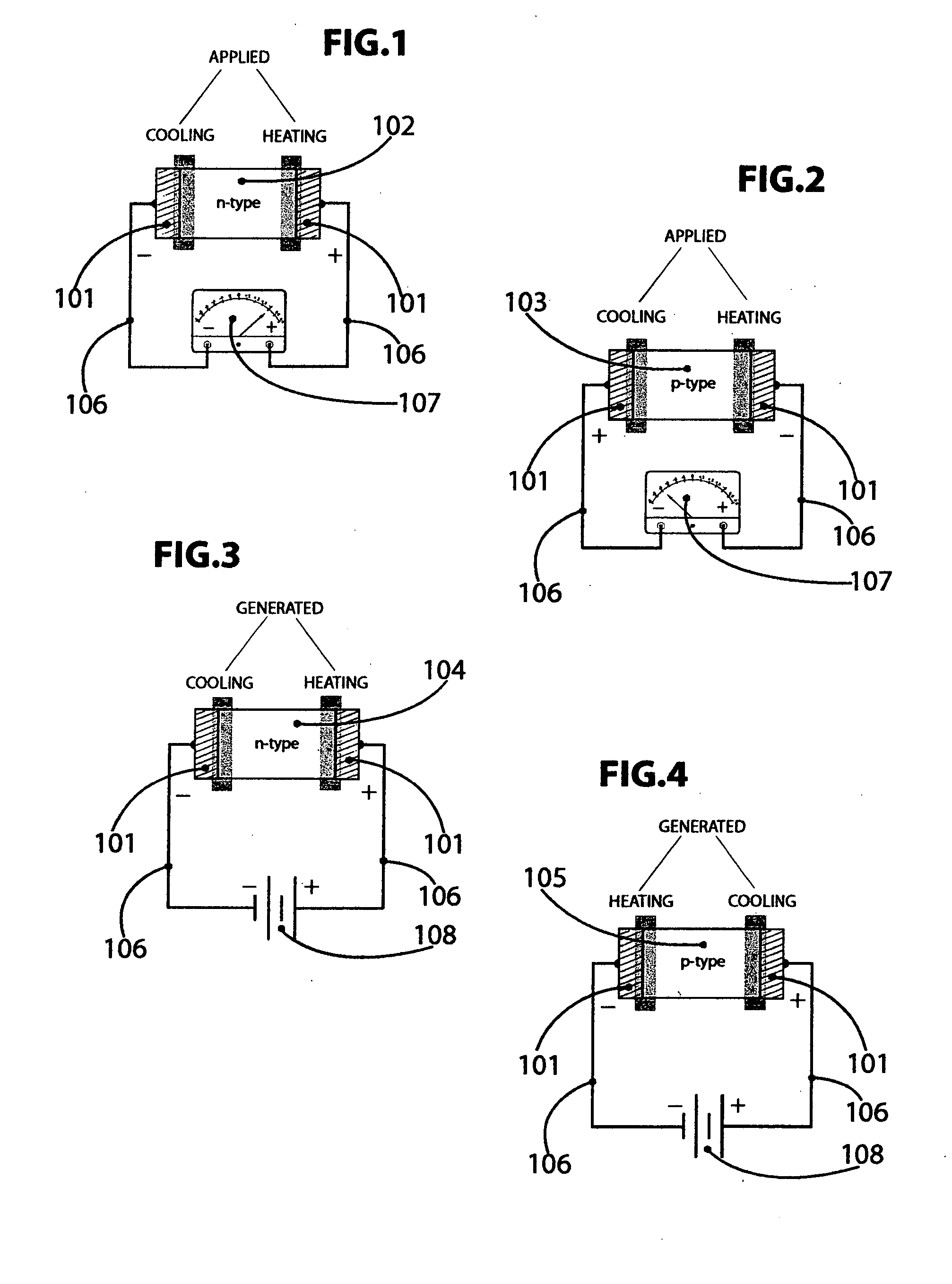
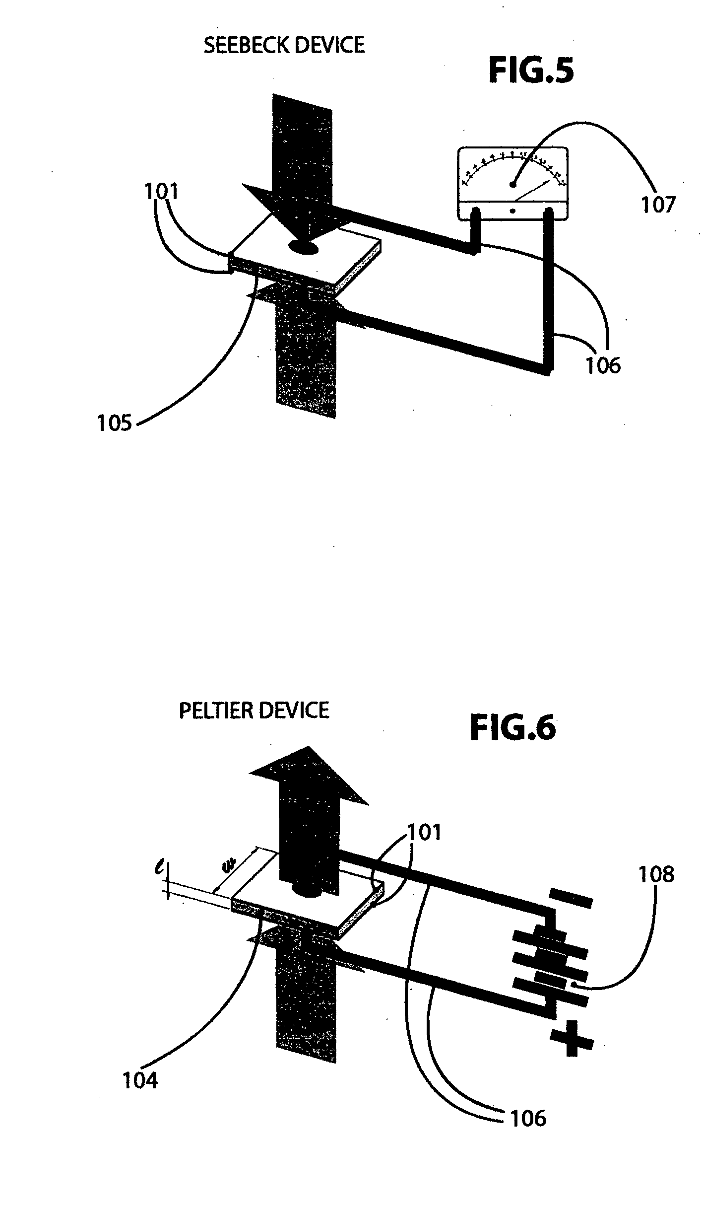
The present invention is embodied in a pair of electrically connected energy conversion devices. One device, converting thermal energy to electric energy is electrically connected to the second thermally isolated device which is converting electric energy to cooling. Thermal isolation is achieved by using an electrically conducting adiabatic wall which is maintained at constant temperature. The constant temperature of the wall is maintained by removing excessive heat by conduction, convection, or radiation.

Description

[0001] This application relates to Provisional Patent Application No. 60 / 523,278 titled Thermoelectric Heat Exchanger filed on Nov. 18, 2003FIELD OF THE INVENTION [0002] This invention relates to cooling apparatus, and methods for making same. More particularly, the invention is directed to thermoelectric, tunneling or displacement current based electricity generators and sub-ambient cooling devices, attaining high relative efficiency through the use of an electrically conductive adiabatic wall which is disseminating excessive heat. RELATED ART [0003]“Heating” and “cooling” are terms used to describe the absorption and emission of heat from a substance. When a substance is absorbing thermal energy it is heated and when a substance is expelling thermal energy it is cooled. The heat removing process or cooling is called an exothermic event and the heat absorbing process is called an endothermic event. Heating is relatively easy to achieve, cooling is more difficult. [0004] Cooling is ...

Claims


Application Information

Patent Timeline
Patent Type & Authority Applications(United States)
IPC IPC(8): F25B21/02F25J3/00H10N10/01H10N10/10H10N15/00
CPCF25B21/02H01L35/28F25B2321/003H10N10/10
Inventor STRNAD, RICHARD J.
Owner STRNAD RICHARD J
Learn More